© 2006 Schneider Electric All Rights Reserved
63230-500-224A1 PowerLogic
®
Series 800 Power Meter
6/2006 Chapter 5—Communications
EN–37
ENGLISH
2-wire Devices
To daisy-chain the power meter to another 2-wire POWERLOGIC
device, wire the power meter’s RS485 communications terminals to
the matching communications terminals of the next device. In other
words, wire the + terminal of the power meter to the + terminal of the
next device, wire – to –, and shield to shield as shown in Figure 5 – 3.
• If the power meter is the first device on the daisy chain, connect it
to the host device using the
MCI-101 kit (or equivalent RS232 to
RS422/RS485 converter). See “Connecting the First Device” on
page EN–38 in this chapter for instructions.
• If the power meter is the last device on the daisy chain, terminate
it. See “Terminating the Communications Link” on page EN–38 in
this chapter for instructions.
• See Table 5 – 2 on page EN–35 for the maximum daisy-chain
communications distances for 2-wire devices.
4-wire Devices for 2-wire Modbus or Jbus
When wiring Modbus 4-wire communications terminals for 2-wire
Modbus or Jbus, jumper RX+ to TX+ and RX– to TX– as shown in
Figure 5 – 4.
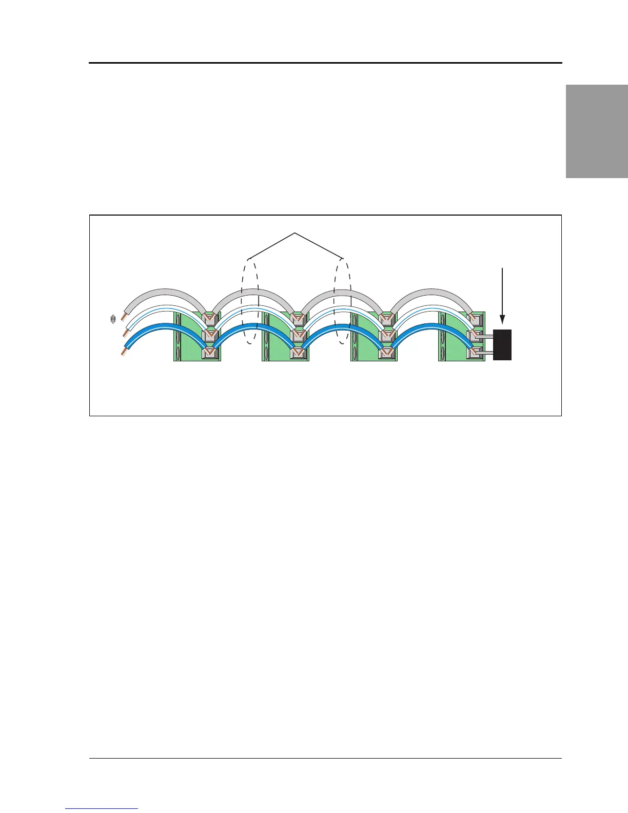
Figure 5 – 3: Daisy-chaining 2-wire devices
–
+
Power Meter 800 or other POWERLOGIC 2-wire compatible devices
Belden 9841 or equivalent
Belden 9841 wire colors: blue with white stripe (+), white with blue stripe (–), and silver (shield)
MCT2W terminator on
the last device of the
daisy chain
PLSD110087