© 2006 Schneider Electric All Rights Reserved
63230-500-224A1 PowerLogic
®
Series 800 Power Meter
6/2006 Chapter 5—Communications
EN–41
ENGLISH
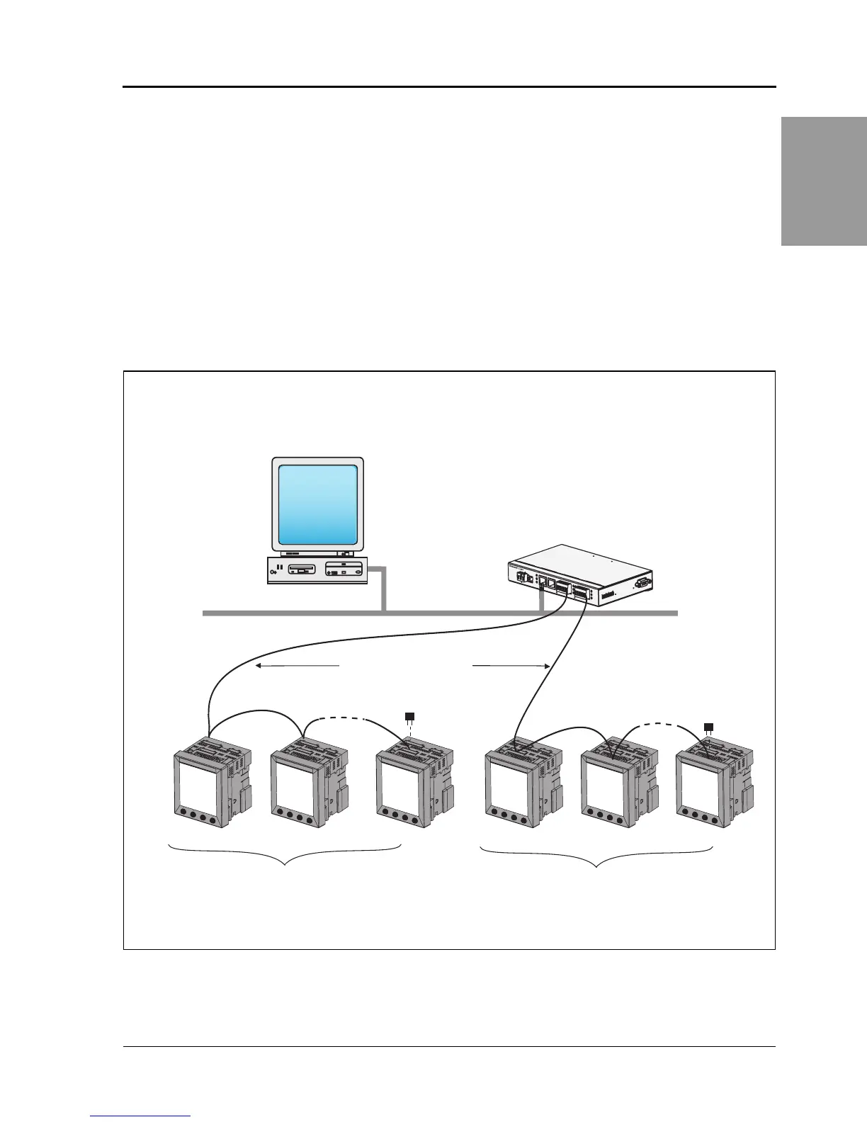
Connecting to an Ethernet Gateway (EGX)
The POWERLOGIC Ethernet Gateway is a network communications
interface that performs protocol conversion between POWERLOGIC-
compatible devices and standard Ethernet network protocols.
An Ethernet Gateway has serial ports that support from 8 to 32
POWERLOGIC devices, depending on the Ethernet Gateway model.
More devices can be daisy-chained when a signal repeater is used.
Refer to the instruction bulletin that ships with your Ethernet Gateway
for more information and installation procedures.
Figure 5 – 7: Power meters connected to Ethernet using a POWERLOGIC Ethernet Gateway
system
L
k
T
x
R
x
C
O
M
1
(R
S
-4
8
5
)
C
O
M
2 (R
S
-4
85
)
RS-485
T
x
R
x
R
x
-
T
x
-
T
x
+
R
x
+
RS-485 Configur
ation
C
OM
2
C
O
M
1
COM 2 (RS-232)
2
1
4
7
9
1
0
8
6
3
5
2
4
V
8
W
10
9
8
7
6
+
10/100 Base
T
5
4
3
2
1
+
R
x
-
T
x
-
T
x
+
R
x
+
100 Base FX
POWERLOGIC
Network Server
with Client
POWERLOGIC
Ethernet Gateway (EGX)
Ethernet
Belden 9841
or equivalent cable
MCT2W Terminator
1–32 Devices (power meters, Series 3000 or
4000 Circuit Monitors, or other Modbus or
Jbus compatible devices)
1–32 Devices (power meters, Series 3000 or
4000 Circuit Monitors, or other Modbus or
Jbus compatible devices)
MCT2W Terminator
PLSD110081