© 2006 Schneider Electric All Rights Reserved
PowerLogic
®
Series 800 Power Meter 63230-500-224A1
Chapter 5—Communications 6/2006
EN–42
ENGLISH
Power Meter With Remote Display Communications Capabilities
The communications port on the remote display adapter can be
configured to operate as a 2-wire, RS485 port; a 4-wire, RS485 port;
or a RS232 port.
NOTE: The 4-wire, RS485 configuration is useful for integrating
Power Meters into existing 4-wire, RS485 daisy chains because extra
converters (CNV100) are not required.
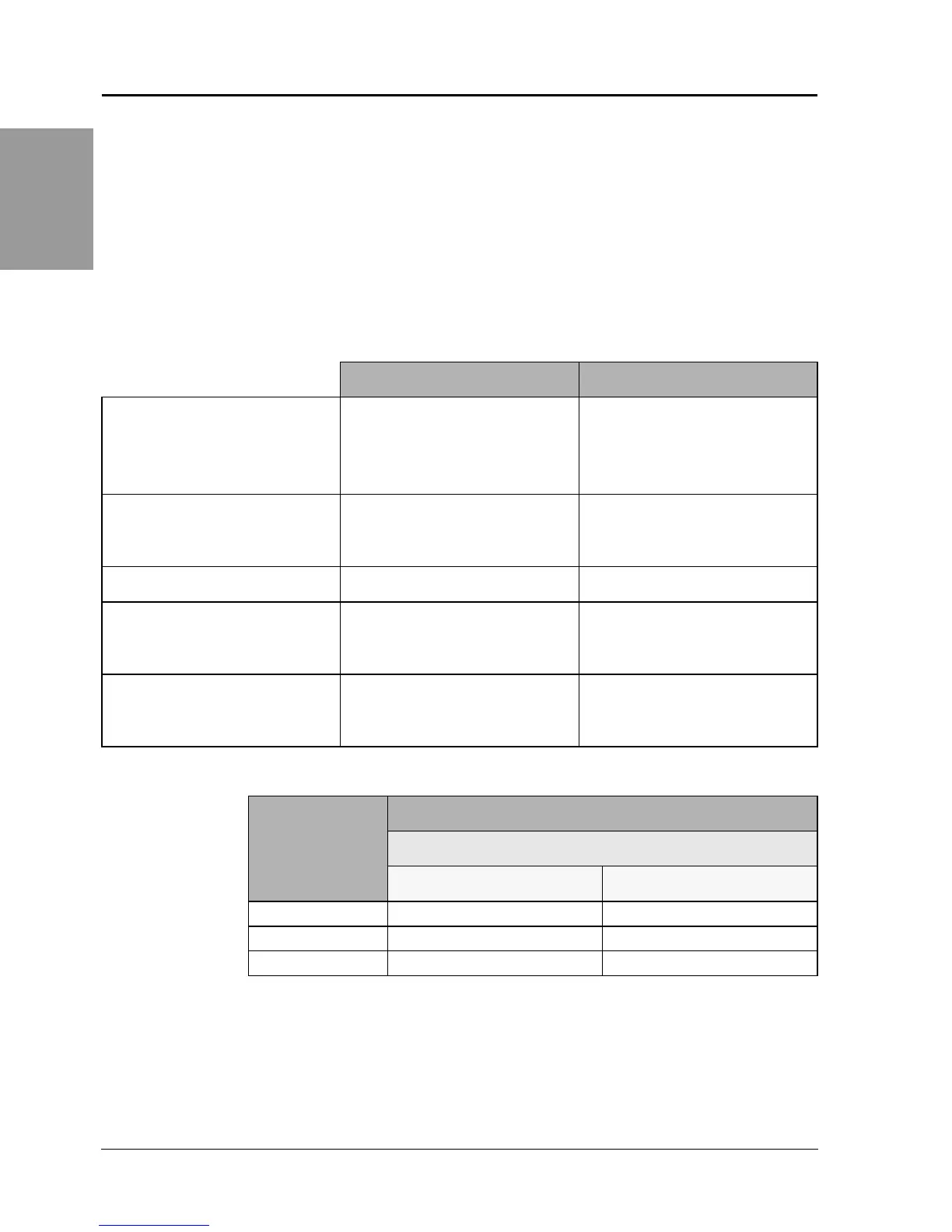
Table 5 – 3: RS485 Port Capabilities
2-wire 4-wire
Communications Port
• 2-wire with shield
• EIA compliant
• Allows the power meter to be
connected to a daisy-chain of up
to 32 devices
• 4-wire with shield
• EIA compliant
• Allows the power meter to be
connected to a daisy-chain of up
to 32 devices
Baud Rate
9600
19200
38400
9600
19200
38400
Communications Distances
See Table 5 – 4. See Table 5 – 4.
Protocols
Modbus RTU
Jbus
7-, 8-bit ASCII
Modbus RTU
Jbus
7-, 8-bit ASCII
Parity
ODD
EVEN
NONE
ODD
EVEN
NONE
Table 5 – 4: 2-wire, RS485 Communications Distances
Baud Rate
Maximum Communication Distances
1 to 32 Devices
Feet Meters
9600 8,000 2,438
19200 6,000 1,829
38400 3,000 914
NOTE: Distances listed should be used as a guide only and cannot be guaranteed for
non-POWERLOGIC devices. Refer to the master device’s documentation for any
additional distance limitations.