139
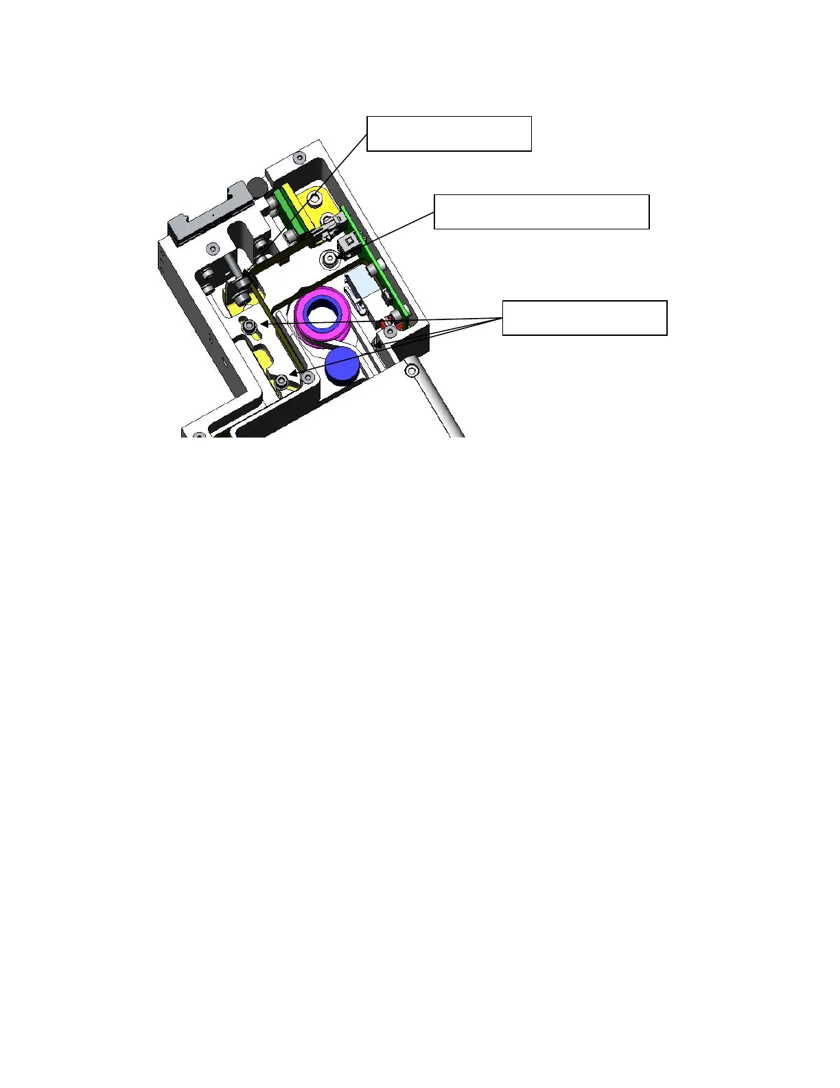
15. Loosen the 3 M3 SHCS and 1 M4 shoulder screw that attach the J2 motor bracket.
16. Measure and record the distance from the back of the Tension Spring to the carriage, then
remove the M4 X 20 SHCD and washer that compress the Tension Spring.
17. Pull the timing belt up over the idler cam follower closest to the large J2 pulley to release belt
tension and provide enough slack to remove the motor
18. If it is necessary to replace the J2 timing belt, replace the belt and reassemble the robot.
Otherwise, skip this step and continue.
19. Now unscrew the 4 Screws and washers that attach the motor mount plate to the Z carriage while
supporting the motor. It may be easiest to leave these screws in the carriage during this
process..
20. Drop the motor assembly downwards while threading the motor cables thru the access hole in the
bottom of the Z carriage, and pulling the timing belt up over the pulley flange.
21. Remove the motor from the Motor Mount Bracket by removing 4 M5 X 12 SHCS. Attach new
motor to Motor Mount Bracket using Loctite 243.
22. Re-install motor, threading cables through the Z carriage first, and pulling timing belt over pulley
flange. Attach motor, with 4 clamping screws. Do not tighten clamping screws all the way.
23. Re-install M4 X 20 Tension Bolt and compress Tension Spring to previous value. Tighten M4
Jam nut to lock bolt and Tension Spring. This will cause motor assembly to pivot on the shoulder
screw and will apply tension to the timing belt. Before tightening the clamping screws, rotate the
J2 output pulley back and forth to be sure the timing belt is running true on the output pulley.
24. Tighten the clamping screws. If a Tension Meter is available check the belt tension for a
minimum tension of 150N. (See Appendix D)
25. Re-assemble the robot except for the front cover and top cover.
26. Remove the Calibration Pins from the inside of the front cover extrusion and re-calibrate the robot
following the Calibration Procedure.
3 Clamping Screws
Tension Spring
Clamping Shoulder Screw