PreSonus StudioLive
™
24.4.2
156
Quick Start:
Level
Setting
Overview Controls Connecting
to a
Computer
Scenes,
Presets &
System
Menu
Technical
Information
Trouble-
shooting
& Warranty
Tutorials
8 Tutorials Owner’s Manual
157
Quick Start:
Level
Setting
OverviewControlsScenes,
Presets &
System
Menu
Technical
Information
Trouble-
shooting
& Warranty
Tutorials
Tutorials 8
Software
Universal Control,
Capture, and
Studio One Artist
Hookup
Hookup
Software
Universal Control,
Capture, and
Studio One Artist
Connecting
to a
Computer
Cascading Two StudioLive 24.4.2s 8.98.9 Cascading Two StudioLive 24.4.2s
8.9 Cascading Two StudioLive 24.4.2s
Your StudioLive 24.4.2 can be cascaded with another StudioLive 24.4.2,
using a FireWire cable, to create a single 48-channel console. Because
of the limitations of FireWire, you cannot connect a computer to your
cascaded StudioLives; however, you can cascade one of several FireStudio
family interfaces with a single StudioLive 24.4.2 to add more recording
inputs. This tutorial will guide you through the syncing process and
explain how two StudioLive 24.4.2 function as one 48-channel mixer.
8.9.1 Conguring Multiple Units
1. To cascade two StudioLive 24.4.2s to create a standalone system (without a
computer), connect a FireWire cable from the rst unit to the second unit.
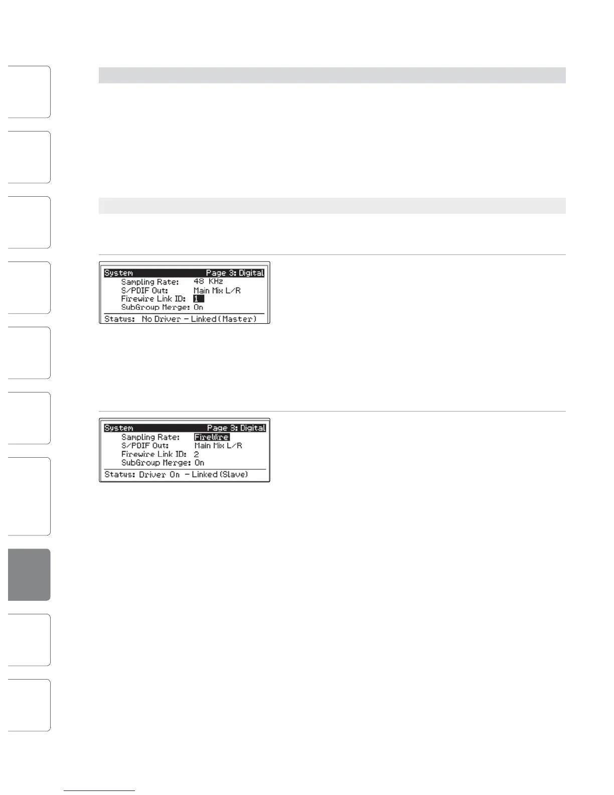
2. Press the System button on the rst unit and page
down to Page 3: Digital. Use the Next button to
move to the Firewire Link ID eld. Use the value
encoder to set the ID to 1. Either unit in the chain
can be designated as the Master. Since both units
will function as one large console, sending all
channels to the Master unit’s Main output, Aux
Sends, and Subgroups (optional), we suggest that
the unit farthest on the right be designated as the
Master. The unit with the lowest Firewire Link ID
greater than zero is automatically set as the Master.
3. Press the System button on the cascaded unit and
page down to Page 3: Digital. Use the Next button
to move to Firewire Link ID eld and give each unit a
unique ID. Any value larger than that of the Master
can be used for the cascaded unit.
8.9.2 Aux Mixing with Cascaded Mixers
Every channel in the mixer chain can be sent to the ten aux outputs on the Master
unit. When you press the Mix button on any of the ten auxes on either mixer, you
will notice that the Mix button for the corresponding aux will illuminate on the
other mixer in the chain. For example, if you press the Mix button on Aux 1 on
the Master unit, the Mix button on Aux 1 on the slaved units will also illuminate.
Creating an aux mix with multiple mixers works exactly the same
way as with one mixer. Each of the encoder beneath the meters in
the Fat Channel control the amount of send level for each of their
corresponding channels on that mixer to the enabled aux.
For example, Channels 1 through 24 reside on the Slave, and Channels 25 through
48 will reside the Master unit. Let’s say that you want to create an aux mix on Aux
3. To begin, press the Aux 3 Mix button on either mixer. The Fat Channel meters
and encoders on both mixers will be ready for you to create an Aux 3 mix. you
will use the Fat Channel meters and encoders on the Slave to set the Aux 3 send
levels for Channels 1-24 and the meters and encoders on the Master unit to set
the Aux 3 send levels for Channels 25-48. The resulting mix is then routed from the
Aux 3 output on the Master unit. If you would like to add Fat Channel dynamics
to the overall Aux 3 mix, simply press the Aux 3 Select button on the Master unit
and use the Master unit Fat Channel to dial in your dynamics and EQ settings.
Note that the aux outputs on the slaved mixer are still active but only have
access to the local channels. So in this example, the Aux 3 mix for Channels 1-24
on the Slave is routed locally to the Aux 3 output and merged with the overall
Aux 3 mix on the Master unit at the same time. Only the Master mixer receives
the merged signals from all cascaded mixers, in addition to its local channels.
Because Aux mixes are sent to the Master unit before the Fat Channel
(for obvious reasons), if you wish to create a stereo Aux mix, you
must link the Aux channels on both of the mixers in the chain in
order to control panning for the channels on the slaved mixer.
8.9.3 Internal Eects Buses
Unlike the 10 Aux buses, the two Internal Eects buses on each mixer are
independent. Using the same example as the previous section, Channels
1-24 can only be routed to EFXA and EFXB on the Slave, and Channels
25-48 are processed using the Master unit’s two internal eects buses.
The advantage is that you get twice the number eects buses!
Of course, if you’d like to send all channels to the same eect, you can
simply load the same eect on both mixers. But with some careful
patching, you can take advantage of the extra eects buses at you disposal.
The Internal Eects buses on each mixer can be assigned to the Master
Unit’s Main output, or to a Subgroup, as usual. Simply select the Eects
bus and press the desired assignment button in the Fat Channel.
 Loading...