PreSonus StudioLive
™
24.4.2
48
Quick Start:
Level
Setting
Overview Connecting
to a
Computer
Scenes,
Presets &
System
Menu
Technical
Information
Tutorials Trouble-
shooting
& Warranty
Controls
4 Controls
48
Owner’s Manual
49
Quick Start:
Level
Setting
OverviewScenes,
Presets &
System
Menu
TutorialsTechnical
Information
Trouble-
shooting
& Warranty
Controls
Controls 4
49
Software
Universal Control,
Capture, and
Studio One Artist
Hookup
Hookup
Software
Universal Control,
Capture, and
Studio One Artist
Connecting
to a
Computer
Digital Eects | Master Control 4.84.7 Master Section
4.7.5 Monitor Bus
The StudioLive features a headphone output and control-room outputs,
giving you the ability to monitor multiple sources on the StudioLive. The
Monitor bus on the StudioLive allows you to monitor the main outputs, Solo
bus, main FireWire return from your computer, and the stereo analog tape
input. Because the Monitor Bus is a summing amp, you can even monitor
the World Series on your headphones while running sound at a show.
Solo Bus Monitor Button Assigns the Solo Bus to the Monitor Outputs.
The Solo Bus Monitor button patches any soloed channel, subgroup, or aux send to
the Monitor bus. This can be useful in any number of ways. For example:
t Auditioning an aux-send monitor mix
t Dialing in the dynamics processing and EQ on a subgroup
t Creating a better blend for instrumental sections (horns, strings, etc.)
Headphone Output Adjusts the Overall Level of the Headphone Output.
Level Control
This knob adjusts the overall level for the headphone output.
Control-Room Monitor Adjusts the Overall Level of the Control Room Monitor Outputs.
Level Control
This knob adjusts the overall level of the control-room monitor outputs.
Tape-Input Monitor Assigns the Tape-Input Signal to the Monitor Bus.
Button
The Tape monitor button routes the signal from the tape inputs (tape returns) to the
monitor bus. The level for this input is controlled by the knob in the 2 Track In section.
Main Mix Monitor Assigns the Main Mix to the Monitor Bus.
Button
The Main Mix Monitor button routes the same signal that is being sent from the
main outputs to the Monitor bus. This signal is always pre-fader.
FireWire Monitor Button Assigns the Main Left/Right FireWire Return to the Monitor Bus.
The FireWire Monitor button patches the main left/right FireWire return (that is, the
signal from your audio software’s master outputs) to the monitor bus. The level for
this input is controlled rst by the level set from the computer application
producing the audio (e.g., Studio One) and then by a knob in the 2 Track In section.
4.8 Digital Eects | Master Control
From the Digital Eects | Master Control section, you can select and
change the parameters of the two internal eects processors, and you
can store and recall every setting on your StudioLive. (See Section 5,
"Scenes, Presets, and System Menu.") Because almost all of the StudioLive’s
features are controlled from the mixing surface (rather than using menus
and submenus), you will mainly use this section to adjust the internal
eects processors and to save and recall presets and Scenes.
4.8.1 The Digital FX (Eects) Menu
The StudioLive features two internal eects processors. Each processor can access
the StudioLive’s selection of high-quality reverbs and delays. As described in
Section 8.4, each of these eects can be routed to any of the subgroups, the aux
bus, or the main outputs. To access the eects library and make adjustments to
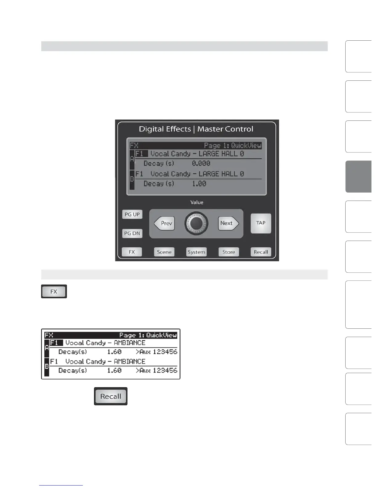
eect parameters, press the FX button in the Master Control section.
The rst page of the FX menu is the QuickView screen.
It displays both of the eects assigned to the internal
eects buses, the main parameter for each, and to
which Aux buses the eect is being routed. Eect A is
assigned to EFX A bus, and Eect B is assigned to EFX
B bus. Use the Next and Prev buttons to navigate
through the screen. To change a parameter, use the
Value encoder directly beneath the LCD screen.
The color will invert for each parameter
when it is selected for modication.
The Next button will scroll through this screen in the following order: FX A library
selection, FX A main parameter, FX B library selection, FX B main parameter. When
choosing your eects preset, use the Value encoder to scroll through the library.