PreSonus StudioLive
™
24.4.2
24
Quick Start:
Level
Setting
Overview Hook-up Connecting
to a
Computer
Scenes,
Presets &
System
Menu
Technical
Information
Tutorials Trouble-
shooting
& Warranty
Controls
4 Controls
24
Owner’s Manual
25
Quick Start:
Level
Setting
OverviewScenes,
Presets &
System
Menu
TutorialsTechnical
Information
Trouble-
shooting
& Warranty
Controls
Controls 4
25
Software
Universal Control,
Capture, and
Studio One Artist
Hookup
Software
Universal Control,
Capture, and
Studio One Artist
Connecting
to a
Computer
The Fat Channel 4.14.1 The Fat Channel
4.0 Controls
4.1 The Fat Channel
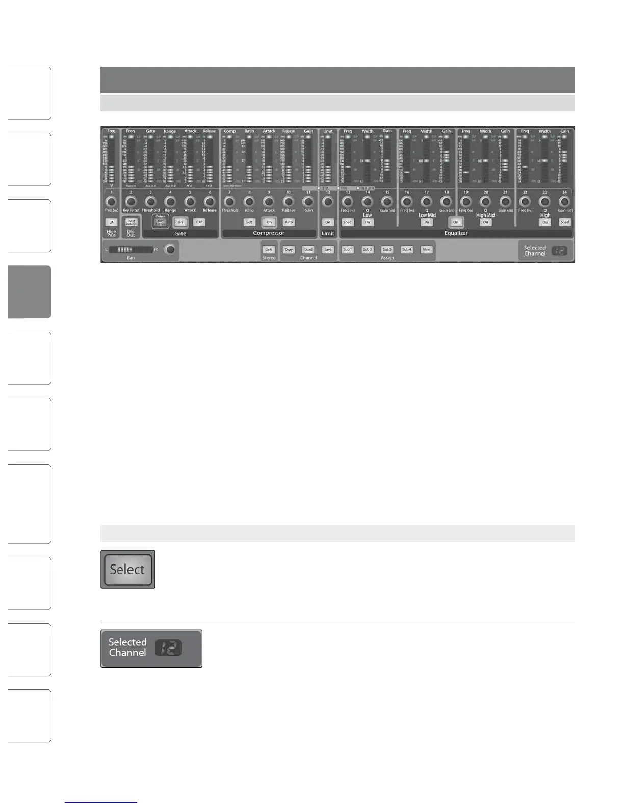
The heart of the StudioLive is the revolutionary Fat Channel. The Fat Channel
makes dynamics, routing, and panning for every input and output on the
StudioLive available at the touch of a Select button. The 24 multipurpose
knobs and meters located in the Fat Channel control nearly every adjustment
you will need to make on your StudioLive. From the Fat Channel, you can:
t Add dynamics processing and EQ to every input and output
t Create sends and effects mixes for all 10 analog aux
sends and both internal effects buses
t Assign subgroup and main routing
t Meter inputs, post-dynamics-processing outputs,
and gain reduction for all 24 channels
t Meter aux-send outputs
t Copy, save, and load mix scenes
t Recall your fader position for stored mixes
4.1.1 Select Buttons, Meters and the Fat Channel
Select Buttons. All around the StudioLive, you will see Select buttons. There is a
Select button on each of the 24 inputs, each of the 10 analog aux sends, both of
the internal eects buses, each of the 4 subgroups, the 2 auxiliary inputs, and the
Main output bus. Each of these buttons serves exactly the same purpose: to access
the Fat Channel parameters for its channel or bus.
Selected Channel Display. In the lower right corner of the Fat Channel, you will
nd an LED readout. The currently selected channel will always be displayed here.
(Numbers 1-24 indicate one of the 24 input channels is selected, S1-S4 indicates
Subgroups 1-4, MA indicates the Main bus, A1-A10 indicates Aux 1-10, A11 and A12
indicate EFX A and EFX B, and F1 and F2 indicate Aux inputs A and B.)
Selected Channel Meters. In addition, two meters—part of a set of seven meters
located in the top right section of the mixer—are dedicated to displaying
information about the currently selected channel. The meter on the far left of this
section displays the pre-fader input level for the selected channel. The meter to the
right of it displays the gain reduction for the selected channel. It is important to
mention that these meters are only active when one of the 24 input channels or an
aux bus is selected.
It should be noted that while the noise gate, compressor, EQ, and limiter are
available on every input and bus, the high-pass lter is only available on the inputs,
10 auxes, and 2 internal FX buses, and the phase reverse is only available on the
24 inputs. In addition, other inputs and buses without Select buttons are available
to route to the auxiliary FireWire returns. (See Section 6.4.2 for more details.)
4.1.2 What You Can Process with the Fat Channel and FireWire Sends.
The following table provides a quick guide to the processing
that is available for each bus in the StudioLive:
Bus Phase
Reverse
High-Pass
Filter
Noise Gate Compressor EQ Limiter FireWire
Send
Inputs (Ch 1-24)
Subgroups
Main Out L/R
Aux Sends 1-10
Internal FX Sends A & B
External FX Returns A & B
Tape Input
Talkback Mic
Solo Bus
Monitor Bus