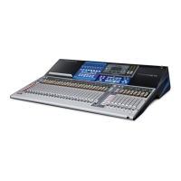
PreSonus StudioLive
™
24.4.2
34
Quick Start:
Level
Setting
Overview Connecting
to a
Computer
Scenes,
Presets &
System
Menu
Technical
Information
Tutorials Trouble-
shooting
& Warranty
Controls
4 Controls
34
Owner’s Manual
35
Quick Start:
Level
Setting
OverviewScenes,
Presets &
System
Menu
TutorialsTechnical
Information
Trouble-
shooting
& Warranty
Controls
Controls 4
35
Hookup
Software
Universal Control,
Capture, and
Studio One Artist
Hookup
Software
Universal Control,
Capture, and
Studio One Artist
Connecting
to a
Computer
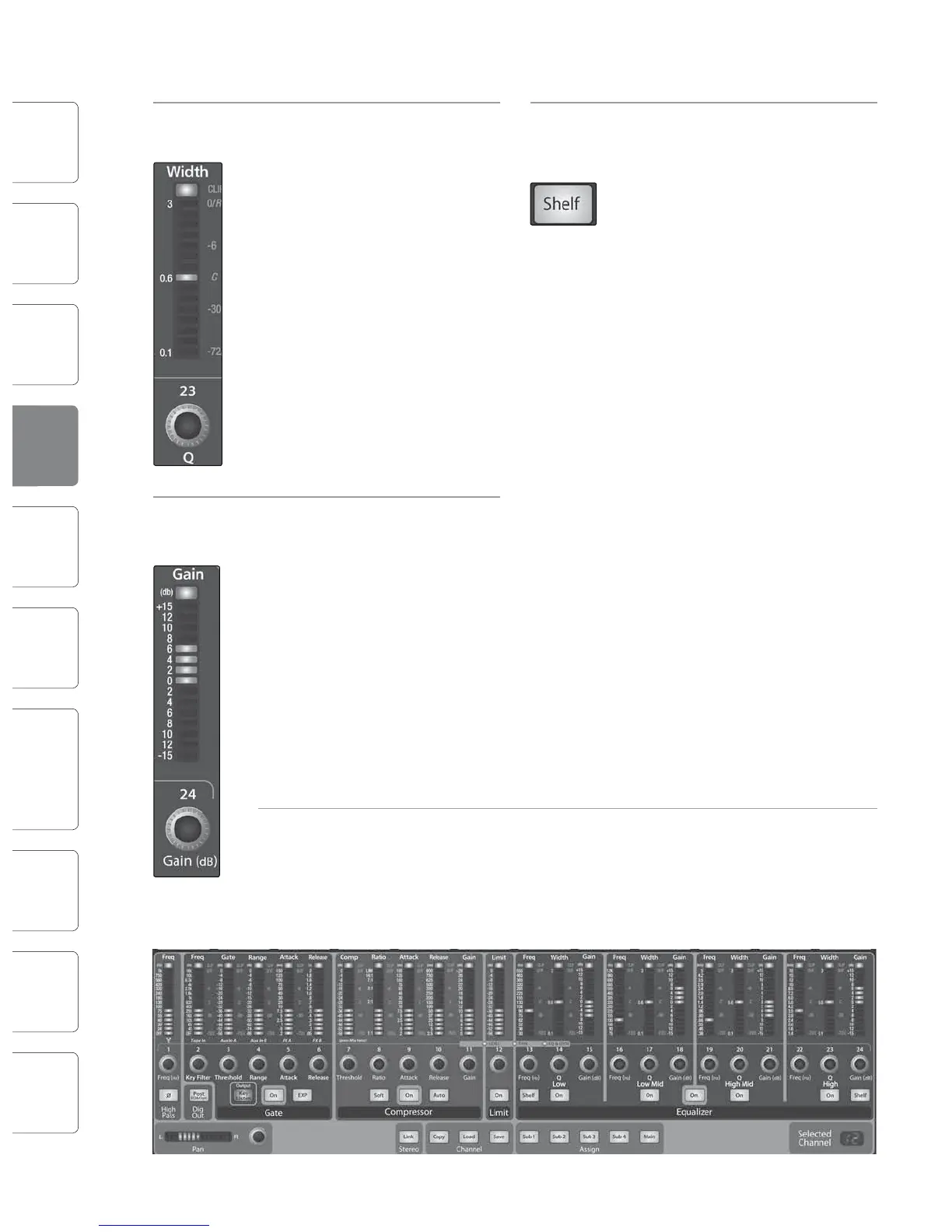
High EQ Q Sets and Displays the Q of the High
Control Frequency Band.
This encoder sets, and the meter
displays, the Q for the High band.
The Q is the ratio of the center
frequency to the bandwidth. When
the center frequency is constant, the
bandwidth is inversely proportional
to the Q, so as you raise the Q, you
narrow the bandwidth.
High EQ Gain Sets and Displays the Gain
Control Attenuation or Boost at the Center
Frequency of the High Frequency
Band.
This encoder sets, and the meter
displays, the gain cut or boost at the
center frequency of the High EQ
band. The level of the center
frequency can be set between -15
and +15 dB.
Limiter Turns on the Limiter for the Selected
On/O Input Channel or Output Bus.
When the limiter is engaged the
button will illuminate. The threshold
for the limiter is set to 0 dBFS. The
Ratio is ∞:1.
High Turns on the High Shelving EQ for
Shelving EQ the Selected Input or Output Bus.
Button
When the Shelf button is not
engaged, the High band is a
parametric EQ. Enabling the Shelf
button turns the High band into a
high shelving EQ that alters, by a
xed amount, a band of low
frequencies at and above a user-
selected shelving frequency.
A high shelving EQ is like a treble-
control knob on a stereo. In this
mode, the Center Frequency control
selects the shelving frequency.
Fat Channel Limiter Section
Limiter Sets and Displays the Threshold of
Threshold the Limiter for the Selected Channel
Control or Output Bus.
This encoder sets, and the meter
displays, the threshold of the limiter
for the selected channel or output
bus. When the signal’s amplitude
(level) exceeds the threshold setting,
the limiter is engaged. Turning the
knob counterclockwise lowers the
threshold, so limiting begins at a
lower amplitude. The threshold can
be set from -56 to 0 dB.
4.1.4 Fat Channel Panning and Stereo Link
The Pan Control for each Input or Output bus is set on
the Fat Channel. The LED display shows the Pan
setting, and the encoder to the right of the display
controls panning for the selected input or output bus.
When two channels are linked as stereo pair, the LED
display will automatically change to stereo pan.
Stereo linking is done within the Fat Channel. Input channels, aux buses, and
subgroups can be linked to create a stereo pair. The stereo pairs are predened and
cannot be changed. They are as follows:
Channels 1 and 2
Channels 3 and 4
Channels 5 and 6
Channels 7 and 8
Channels 9 and 10
Channels 11 and 12
Channels 13 and 14
Channels 15 and 16
Channels 17 and 18
Channels 19 and 20
Channels 21 and 22
Channels 23 and 24
Aux 1 and Aux 2
Aux 3 and Aux 4
Aux 5 and Aux 6
Aux 7 and Aux 8
Aux 9 and Aux 10
Subgroups 1 and 2
Subgroups 3 and 4
A stereo link can be enabled when either channel in the pair is selected.
When the Stereo Link button is illuminated, all dynamics settings, subgroup
assignments, and main assignments are pasted to the other channel in the pair.
Note that this is a nondestructive paste; when the Link button is disengaged,
the other channel‘s previous settings will be restored. For instance, if Channel 8
is selected when the Stereo Link button is engaged, all of Channel 8’s settings
will be copied onto Channel 7. If Channel 7 is selected when the Stereo Link
button is engaged, Channel 7’s settings will be copied onto Channel 8.
Note: See Also Graphic Equalizers, Section 5.3
Fat Channel 4.14.1 The Fat Channel