2–19
Principles of Operation
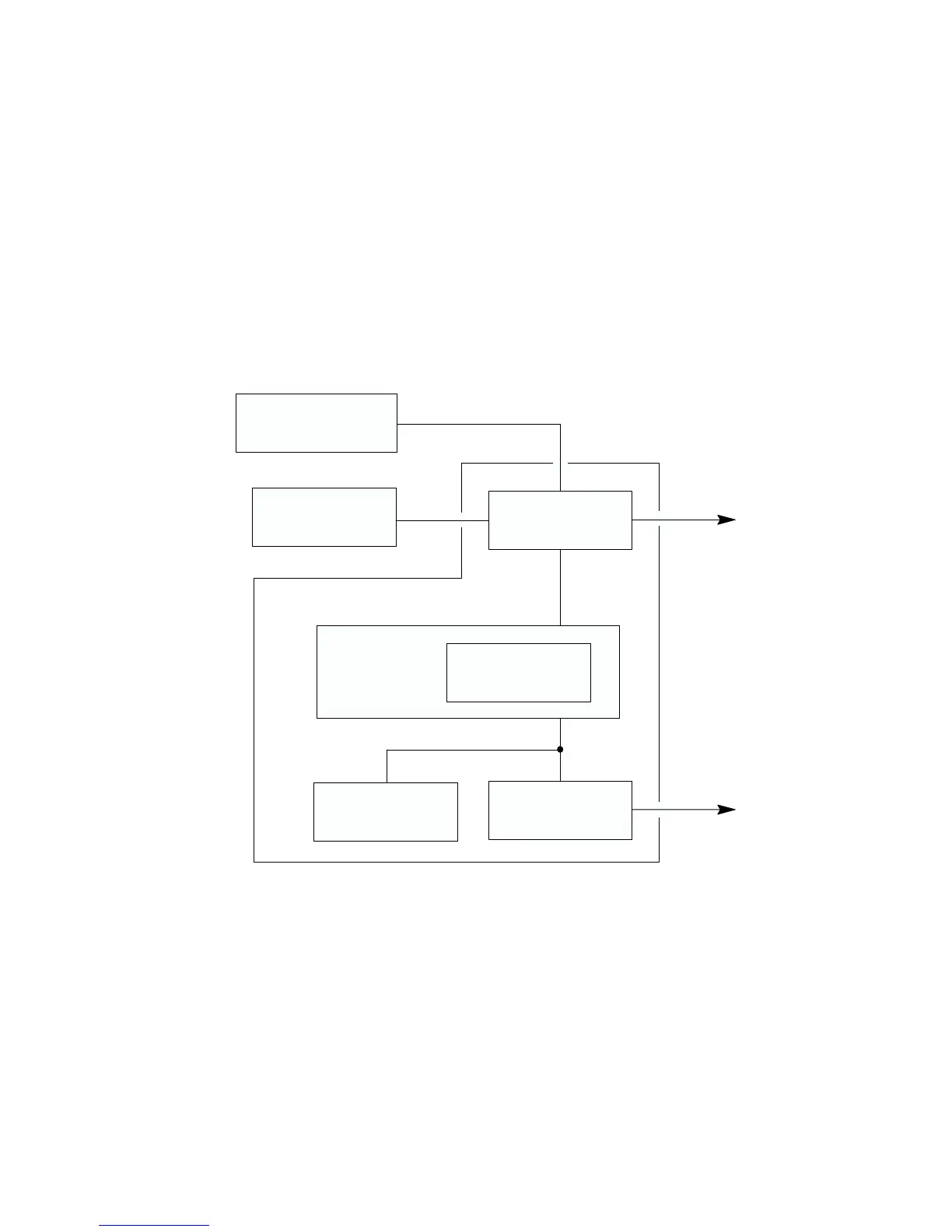
Hammer Driver Interface Functions
In order to print a dot image, two things must happen. First, the dots must get
to the hammers one dot row at a time and in the correct sequence. Second,
the hammers must be fired at the appropriate time in the stroke of the shuttle.
The RTPU microprocessor controls both of these functions, but each is
actually performed by an application–specific integrated circuit (ASIC)
containing hardware dedicated to the function. These ASICs are the Dot
Plucker Memory Controller (DPMC) and the Fire Timer IC (FTIC). The
hammer driver interface functions of the RTPU are summarized in
Figure 2–13.
DATA PROCESSING
RTPU
REAL–TIME PROCESSING UNIT
UNIT
PROCESSOR
DMA Controller
Dot Plucker
Fire Timer
EPROM
SHARED MEMORY
Hammer
Driver
Data
Hammer
Timing
Data
ASIC
ASIC
Figure 2–13. Hammer Driver Interface Functions of the RTPU
Getting Dots to the Hammers Getting dots to the hammers consists of
going into the shared memory and pulling bits out in a given order and
shifting them to the hammer driver at the correct time. This process is called
“dot plucking.” The order in which dots are plucked from memory depends
on the dot density, the number of dots per hammer, the number of hammers
on the hammer bank, the number of phases, and other factors. These factors