19
Parameters | General
User Manual | Agrónic 2500
5.3. GENERAL
The pump, fertilizers, filter and diesel outputs are con-
figured in this section.
The outputs can be from the base of the Agrónic 2500, a
recommended option and from external modules such
as the AgroBee-L, an option not recommended due to
the activation and deactivation delays they may have.
Pumps
Output connected to the drive pumps or general valves.
GENERAL PARAMETERS
Pump 1: yes
Temp. start: 018”
Temp. stop: 012”
Stopping the sectors: no
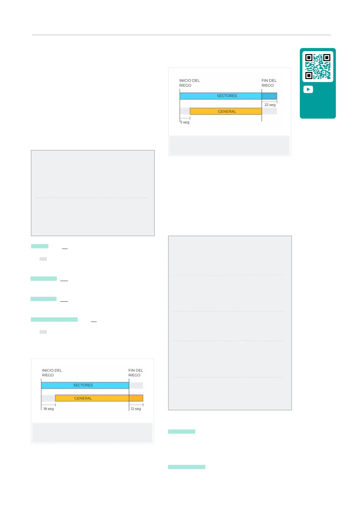
Pump 2: yes
Temp. start: 005”
Temp. stop: 022”
Stopping sectors: yes
Pump 1 (yes | no):
• Yes: i f pump 1 output is to be used. An output must
be assigned to the pump.
Temp. start (000 ... 250”): time delay in activating the
pump when starting an irrigation.
Temp. stop (000 ... 250”): time that the pump stop is
extended when stopping irrigation.
Stopping the sectors (yes | no):
• Yes: for the pump to stop when irrigation is finished
and for the sectors to remain open for a few more
seconds.
Start timing: 018
Stop timing: 012
Stop in the sectors: no
Start timing: 005
Stop timing: 022
Stop in sectors: yes
Outputs
At the base of the Agrónic 2500, there can be up to 27
digital outputs, identified as R1 to R27, to connect the
general outputs. It is recommended to start with the
unit’s last outputs and reserve the first ones for the
sectors.
GENERAL PARAMETERS
Assign outputs:
Pump 1: 00018
Pump 2: 00017
F1: 00015
F2: 00014
F3: 00013
F4: 00012
Fertilizer:
Pump: 00016
Cleaning: 00020
A1: 00000
A2: 00011
A3: 00000
A4: 00000
L1: 00010
L3: 00007
GL: 00000
Pumps
P1 and P2 : outputs connected to pumps or general
valves.
Fertilizers
F1, F2, F3, F4 : outputs connected to the fertilizer
injectors.
Video tutorial
available for
this section