CAUTION!
Pump may be damaged.
IP65 degree of protection cannot be guaranteed if
the CAN cable is not correctly screwed in.
– Manually screw in the CAN cable threaded
connectors until they reach the stop.
The following requirements apply to the connecting cables /
Modbus interface:
n half-duplex, 2-wire technology, “twisted pair” cable
n Max. cable length 1200 m
n RS-485 (TIA-485-A)
n Differential voltage level ± 5 V
n Active termination (terminating resistor)
If the Modbus pump is connected to the end of the
Modbus, the integrated terminating resistor of the
PCB can be switched on via the metering pump's
menu - there is then no need for a separate termi‐
nating resistor screwed to the end.
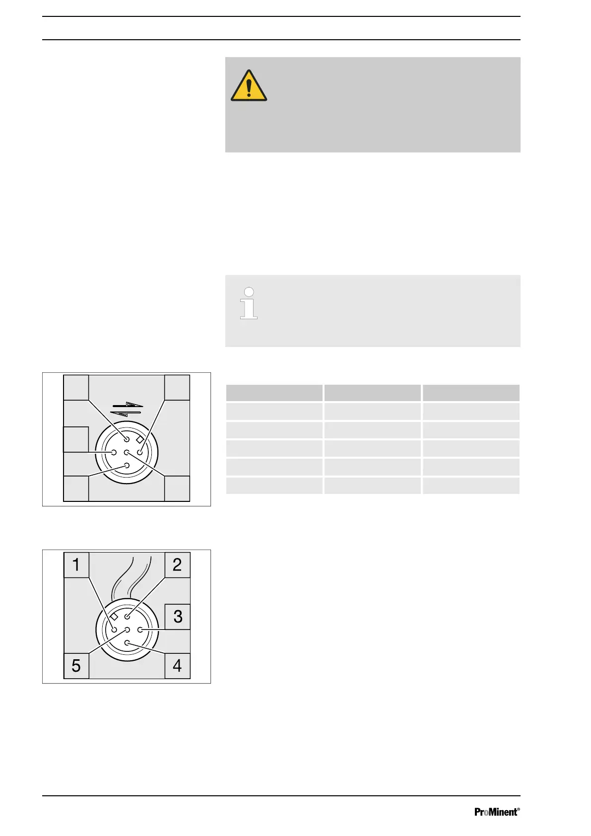
Tab. 23: Connection assignment for Modbus RTU
Pin Lead colour PLC terminal
1 - -
2 - -
3 blue GND
4 black A/+
5 grey B/-
Fig. 6: Socket assignment on the
pump
Fig. 7: Plug assignment on the CAN
cable
Supplementary operating instructions for Modbus RTU
28

 Loading...