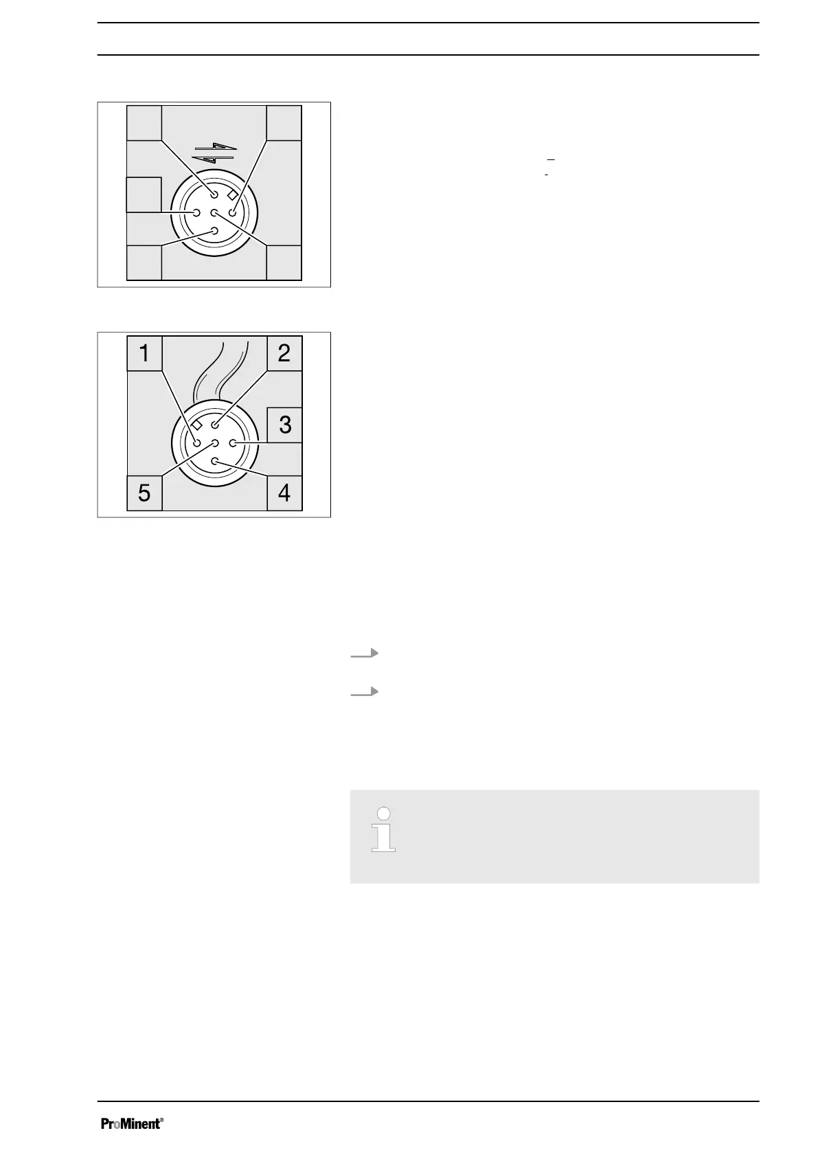
A five-pin plug is used as the “CANopen bus connector”.
1 Shield
2 CAN V+ (supply voltage – not connected)
3 CAN GND (reference potential)
4 CAN H (bus line – dominant high
)
5 CAN L (bus line – dominant
low
)
1.4 Emergency mode
You can guard against the possibility of the CANopen bus control
failing as follows:
1. Program an auxiliary frequency into the pump that fits best
with your process in emergency mode.
2. As soon as emergency mode is required, run the pump using
the "external control" terminal on the auxiliary frequency -
see "Operating instructions for the peristaltic metering
pump DULCO flex Control, DFXa" - "Installation, elec‐
trical".
Doing this will require an external cable and equip‐
ment to issue the auxiliary signal.
If you are in any doubt, seek the advice of our
technical support team.
1.5 Troubleshooting
The CANopen status LED indicates the status of the CAN connec‐
tion.
Operating and fault statuses are displayed by the 3 other LEDs -
see "Operating instructions for peristaltic metering pump DULCO
flex control DFXa”.
Connector for CANopen bus
Fig. 3: Pump pin assignment (plug)
Fig. 4: CAN cable assignment
(socket)
Supplementary operating instructions for CANopen
7
 Loading...