
C
Courtney RamirezSep 1, 2025
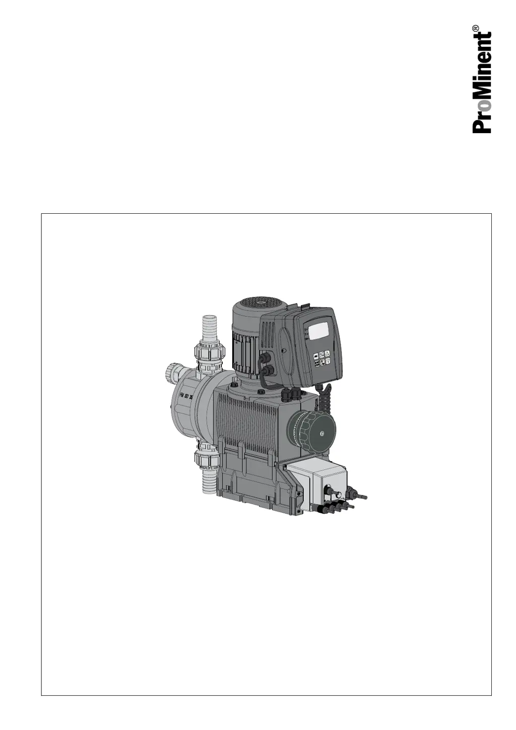
Why is the "Temperature" symbol flashing on my ProMinent Sigma/ 2 Control S2Cb Water Pump's LCD screen?
- JJason HintonSep 2, 2025
If the "Temperature" symbol C FC is flashing on the LCD screen and the error message „Temperature FC“ E47-4 appears, causing the pump to stop, it indicates that the pump is overloaded or the temperature is too high. Rectify the cause, then press the [P/OK] key.


