Installation and setup
Page C-6 Operator’s Manual PiCCO
2
Version 3.1
3 Setup and measurement: Step by step
3.1 Connectors and connections
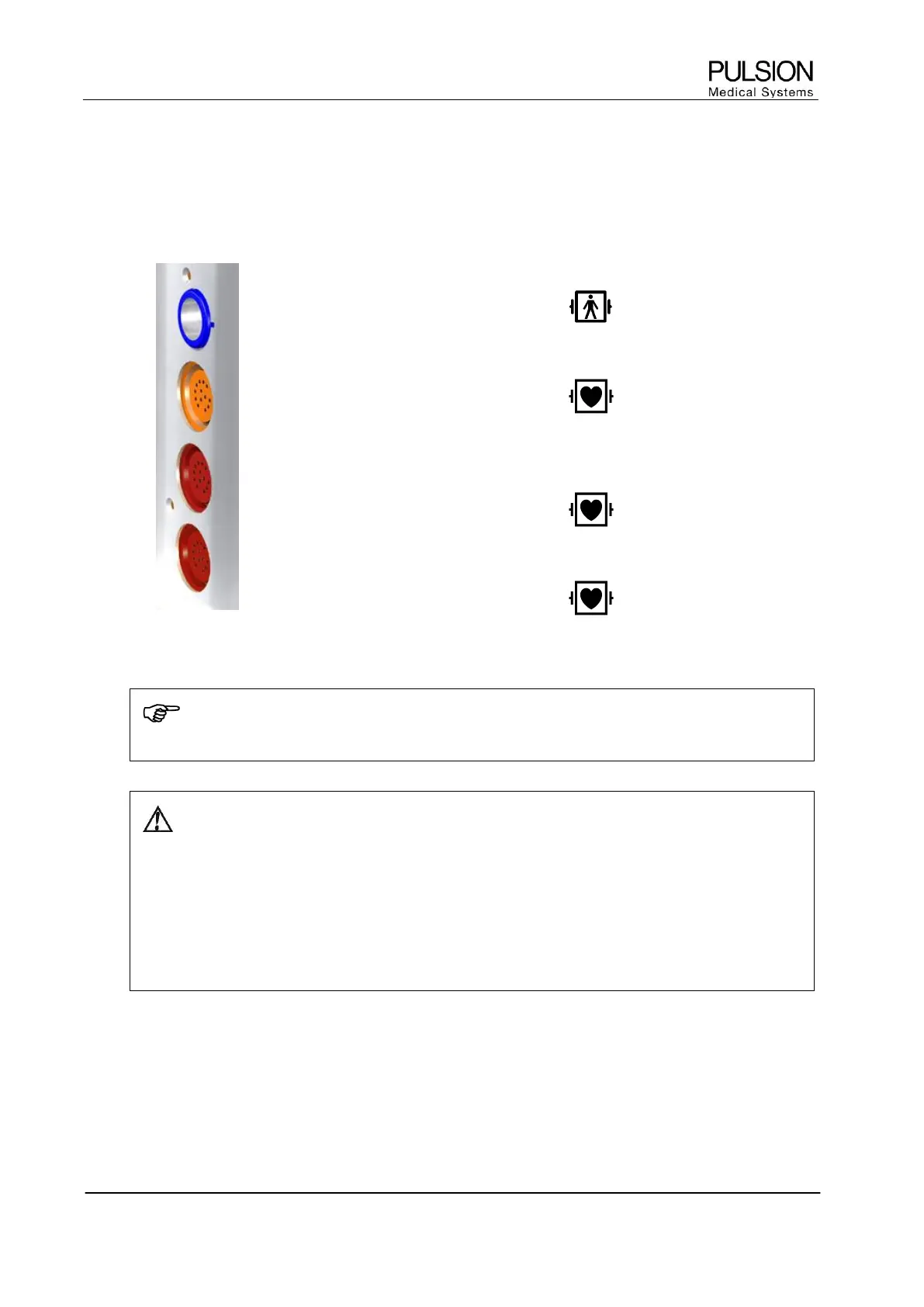
3.1.1 Patient cables
SO
2
Connection of the CeVOX module or
LiMON module
CO
Connection of temperature interface cable
for arterial thermodilution catheter and
injectate temperature sensor.
AP
Connection of pressure transfer cable for
arterial pressure (AP)
CVP
Connection of pressure transfer cable for
central venous pressure (CVP)
Figure 14: Patient cables socket with equipment class (defibrillator protection)
NOTE
PiCCO
2
is protected against electric shock in case of defibrillation.
WARNING: Do not use damaged probes or patient cables. Do not use any probes with exposed
optical or electrical components.
Do not reconnect the PiCCO
2
to electrical power if liquid has entered the device. A short circuit
may damage the device and cause hazardous conditions for patient and user.
Remove patient cables which are not needed. The used components are not galvanically isolated
from each other.
Place the cables attached to the patient carefully so that the patient is not in danger of becoming
entangled or strangulating him/herself with the cables.