Installation and setup
Operator´s Manual PiCCO
2
Page
Version 3.1 C-7
3.1.2 Monitor connections
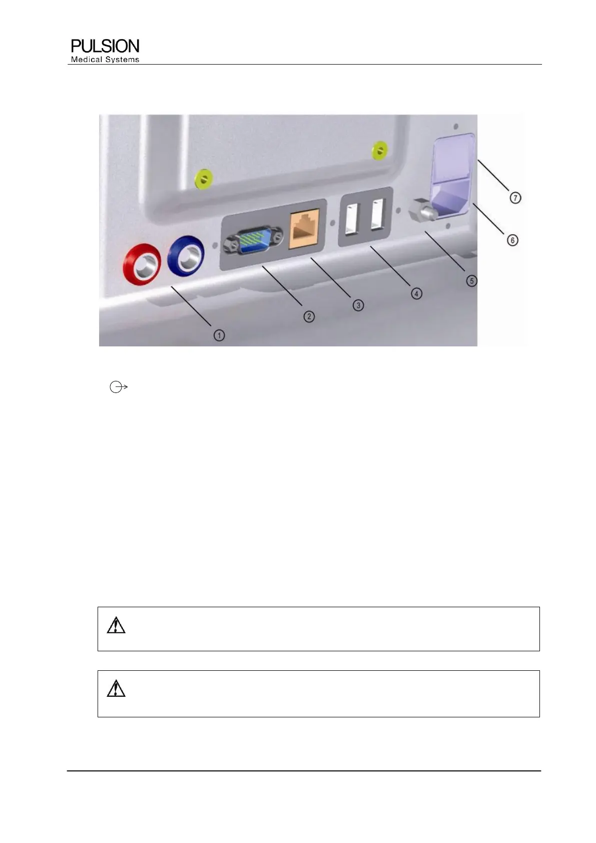
Figure 15: Monitor connections
1) AP / CVP
Transfer of continuous arterial pressure (AP) and central venous pressure (CVP) signal to bedside monitor
2) Serial Interface RS232
Connection for patient data acquisition systems (PDMS)
3) LAN
Connection for network devices for printing and data transfer
4) USB ports (2)
Connection for external printer and PULSION memory stick
5) Potential equalization
Connection for potential equalization cable
6) Mains power connector
Connects the monitor to the power socket
7) Mains switch
WARNING: Connect the potential equalization at the back of the device with the potential
equalization system of the treatment room.
CAUTION: Any additional item of equipment which is connected to the digital interface
must satisfy the requirements of the current IEC specification.