Sterling 10 Installation Manual
RINS1413-1 Page 9
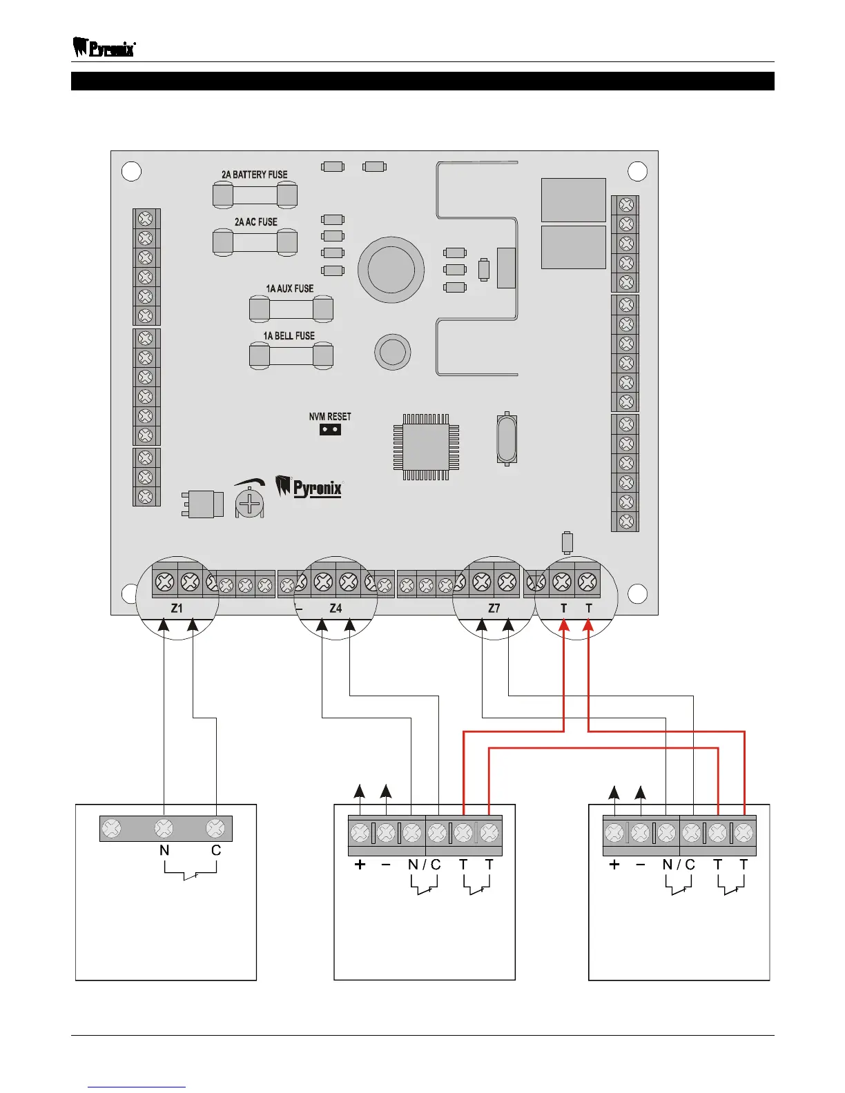
2.8 Detector Connections
NOTE 1: Any unused zones must be linked out.
NOTE 2: The tamper connections from each detector must be connected in SERIES.
R
R
TUFSMJOH
10
+BAT–
SPEAKER
VOLUME
-+
17V~
– – – – – –DIGITAL COMMUNICATOR– – – – – –
LNF
SET CON
ABT FIRE ALM PA
PGM1 PGM2
+SPK–
Z1 Z2 Z3 +AUX– Z4 Z5 +AUX– Z6 Z7 Z8 T T
PA PTS +BELL–
BT
– – – – –KEYPAD– – – – –
KD KT K+ K–
– – – –BELL– – – – – – –STROBE– –
NO NO
C
C
NC
NC
Spare
ALARM
Magnetic
Contact
Zone 1
Zone
 Loading...