Sterling 10 Installation Manual
Page 4 RINS1413-1
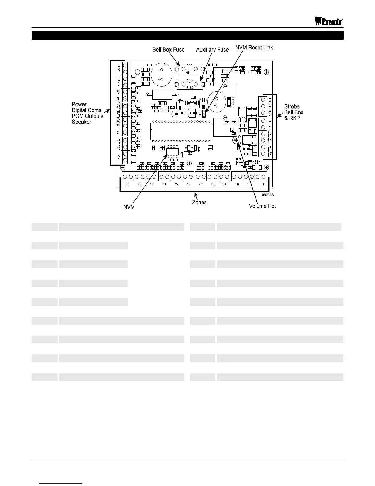
2.2 Transistor PCB Layout & Terminal Connections
+BAT- Connections for Battery Z6 Programmable Zone
17V 17V AC Supply Z7 Programmable Zone
LNF Line Fail Z8 Programmable Zone
SET Open/Close +AUX- Auxiliary Supply
CON Confirmed Alarm T Tamper Terminal
ABT Abort T Tamper Terminal
FIRE Fire Alarm PA Personal Attack
ALM Alarm PTS Push To Set
PA Personal Attack Alarm
DigiCom
Outputs
KD Keypad Data
PGM1 Programmable Output 1 KT Keypad Tamper
PGM2 Programmable Output 2 K+ Keypad Positive
+SPK- Speaker Output K- Keypad Negative
Z1 Programmable Zone B+ Bell Positive
Z2 Programmable Zone B- Bell Negative
Z3 Programmable Zone STB Strobe Trigger
Z4 Programmable Zone BA Bell Trigger
Z5 Programmable Zone BT Bell Tamper
 Loading...