Sterling 10 Installation Manual
RINS1413-1 Page 3
2. WIRING DIAGRAMS
NOTE: If a PA button is NOT connected to the system, you MUST link out the PA terminals on the
PCB.
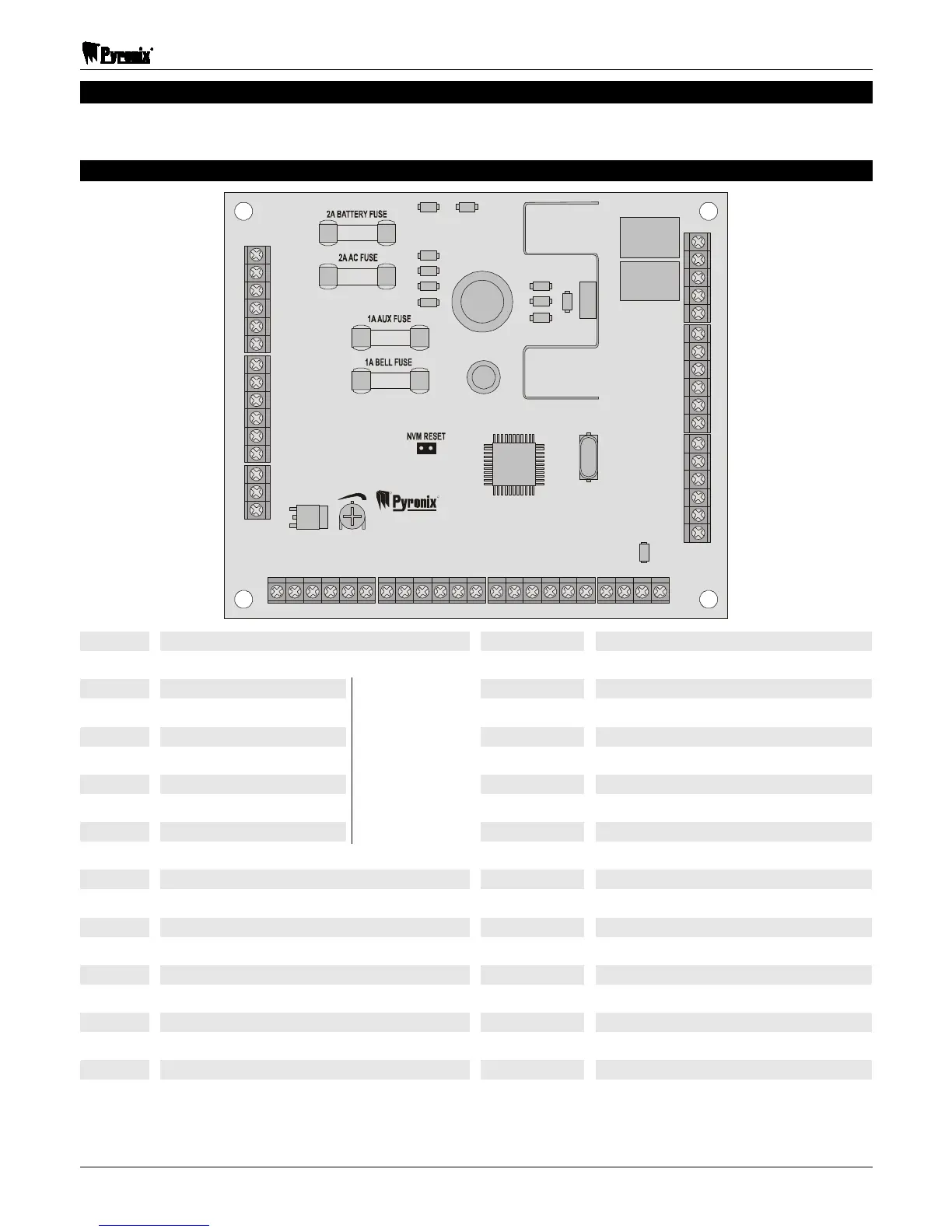
2.1 Relay PCB Layout & Terminal Connections
R
R
TUFSMJOH
10
+BAT–
SPEAKER
VOLUME
-+
17V~
PGM1PGM2
+SPK–
Z1 Z2 Z3 +AUX– Z4 Z5 +AUX– Z6 Z7 Z8 T T
PA PTS +BELL–
BT
– – – – –KEYPAD– – – – –
KD KT K+ K–
– – – –BELL– – – –
– – –STROBE– –
NO NOCCNC NC
+BAT- Connections for Battery Z7 Programmable Zone
17V 17V AC Supply Z8 Programmable Zone
LNF Line Fail T Tamper Terminal
SET Open/Close T Tamper Terminal
CON Confirmed Alarm PA Personal Attack
ABT Abort PTS Push To Set
FIRE Fire Alarm KD Keypad Data
ALM Alarm KT Keypad Tamper
PA Personal Attack Alarm
DigiCom
Outputs
K+ Keypad Positive
PGM1 Programmable Output 1 K- Keypad Negative
PGM2 Programmable Output 2 +BELL- Bell Supply
+SPK- Speaker Output BT Bell Tamper
Z1 Programmable Zone Bell NO Bell Normally Open
Z2 Programmable Zone Bell C Bell Common
Z3 Programmable Zone Bell NC Bell Normally Closed
+AUX- Auxiliary Supply Strobe NO Strobe Normally Open
Z4 Programmable Zone Strobe C Strobe Common
Z5 Programmable Zone Strobe NC Strobe Normally Closed
Z6 Programmable Zone
 Loading...