1. INSTALLATION PROCEDURE
The Sterling 10 is packaged with the transformer and tamper switch. The speaker cover (if a speaker is used),
tamper switch pin and cable knock-outs should be removed from the panel prior to fixing to the wall. The
following steps illustrate the basic setup procedure for mains and battery connection.
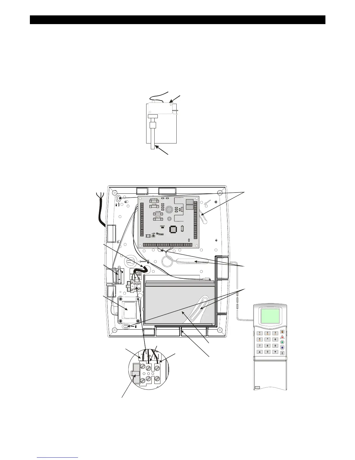
Step 1 – Remove the case lid from the control panel and check all parts and components are in place.
Step 2 – Decide where the Sterling 10 panel will be situated. A discrete and concealed place is advisable.
Step 3 – Remove the tamper pin from the case moulding (behind the PCB) and insert into the tamper pin
hole at the rear of the panel.
Tamper Switch
Tamper Pin
Step 4 – Secure the Sterling 10 panel to a sturdy and stable surface, using the mounting screws provided.
First mark the wall where the panel is to be situated (using the mounting holes), drill holes in the wall then
fasten the panel base to the wall with screws supplied.
Live
Earth
Neutral
Battery
Support
Battery
Wall Fixin
Holes
Cable Entry
Holes
To Mains Supply
Mains
Transformer
Tamper
Switch
Mains Cable
Entry Hole
Fuse carrier handle
(fuse nominal - 250mA)
NOTE: When the panel is connected
to mains use fuse csrrier handle to
turn mains power supply on or off
R
R
TUFSMJOH
10
+BAT–
SPEAKER
VOLUME
-+
17V~
– – – – – –DIGITAL COMMUNICATOR– – – – – –
LNF S ET CON ABT F IRE AL M P A
PGM1PGM2
+SP K–
Z1 Z2 Z3 +AUX– Z4 Z5 +AUX– Z6 Z7 Z8 T T
PA
PTS
+BELL–
BT
– – – – –KEYPAD– – – – –
KD K T K+ K–
– – – –BELL– – – – – – –STROBE– –
NO NOCCNC NC
Please note the internal speaker must be a 16ohm speaker.
 Loading...