61
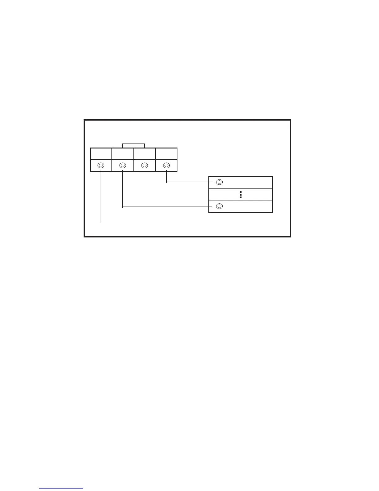
The accompanying diagram (Picture 8-2), along with your alarm’s manual should be
consulted to ensure proper connection.
• Normal open or Normal close type
• Parallel connect COM end and GND end of the alarm detector (Provide external power to
the alarm detector).
• Parallel connect the Ground of the combo DVR and the ground of the alarm detector.
• Connect the NC port of the alarm sensor to the combo DVR alarm input(ALARM)
• Use the same ground with that of combo DVR if you use external power to the alarm device.
PICTURE 8-2
+12V GND COM PC
GND
ALARM
Alarm input public end should jump out with device power end.
Alarm Device Connection Terminal
Alarm Device
Connection Terminal
+12V GND

 Loading...