60
NO C
1
NO C
2
1 2 3 4 5 6 7 8
A B
CNTRL
12V
ALARM IN
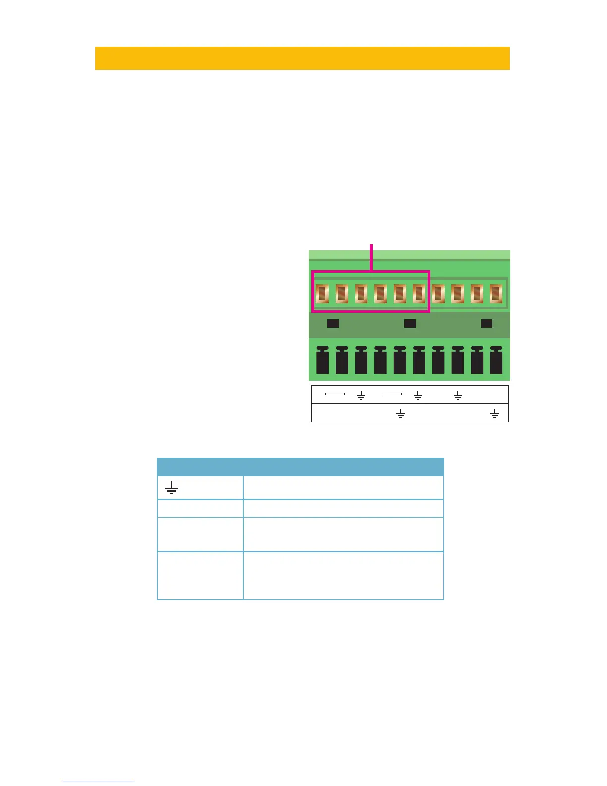
Many QT Series DVRs feature connections for external alarms – both input and output. Please
consult Chapter 2 Connections and Controls to determine whether your model includes
this feature and where the connection block is located. The alarm connector block shown in
Picture 8-1 is only a representation and your actual connector may look different.
When an event is detected the system can notify local users or send notification to a
monitoring service. At the same time, the system can accept signals from motion detectors,
smoke detectors or other alarms and begin recording based on that input and your settings.
You will need to have the manual for your alarm(s) handy to ensure the proper settings within
the DVR.
ALARMS
CHAPTER 8
8.1 ALARM INPUT
When attaching alarms, the following criteria
must be met:
1. The alarm input must be grounded.
2. A grounding signal is required for the
alarm input
3. When connecting the DVR to another
device - including another DVR - through
the alarm input, a relay should be used to
separate them.
Parameter Grounding Alarm
Ground line
Alarm Input 1, 2, …, 8 becomes valid in low voltage.
1-NO C
2-NO C
Two NO activation outputs.
CTRL 12V Controls the power output
You need to close the device power to
cancel the alarm.
PICTURE 8-1

 Loading...