Operation 107
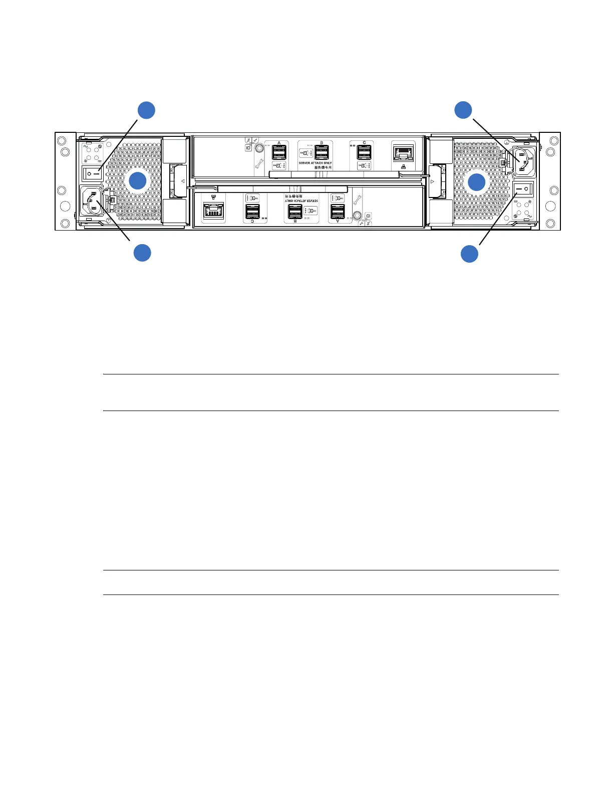
1 Locate the power supply units (PSU0 and PSU1) on the rear of the 2U12/2U24 expansion chassis in
Figure 94.
Figure 94 2U12/2U24 Expansion Chassis (Rear View)
2 Plug the power cords into the power cord receptacles on the rear of the expansion chassis.
3 Plug the other end of the power cords into the rack power source.
NOTE: Each expansion chassis takes approximately 3 minutes to power on (drives to spin up and/or
come online).
4 Turn on (1) the PSU0 power switch and then turn on the PSU1 power switch.
• Expansion chassis powers on within 3 minutes.
• While the expansion chassis power up, their LEDs blink. After the LEDs stop blinking—if no
LEDs on the front and back of the chassis are amber—the power-on sequence is complete, and
no faults have been detected.
• The System Power LED on the 2U Ops panel should be lit green when the chassis power is
activated.
• See 2U Chassis Ops Panel LEDs on page 118 for details pertaining to 2U Ops panel LEDs and
related fault conditions.
NOTE: Repeat these steps for any other expansion chassis within this configuration.
1
4
2
3
5
1
PSU0
2
PSU0 Power Switch
3
PSU0 Power Receptacle
4
PSU1
5
PSU1 Power Receptacle
6
PSU1 Power Switch
 Loading...


