156 QXS G2 Hardware Installation and Maintenance Guide
NOTE: Figure 124 on page 162 provides a representative example of the controllers used in the
RAID chassis.
Figure 125 on page 163 provides a representative example of the IOMs used in the expansion chassis.
The QXS-G2-312, QXS-G2-324, QXS-G2-412, QXS-G2-424, and QXS-G2-484 use the same identical
IOMs.
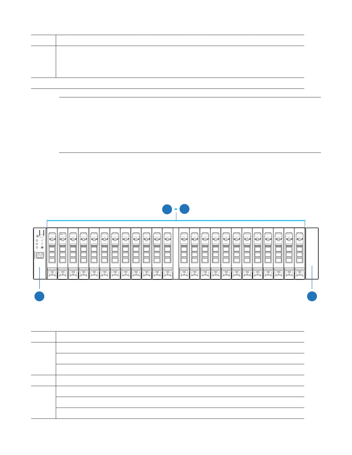
2U24 Expansion Chassis CRUs (Front)
Figure 117 provides the location of the 2U24 expansion chassis CRUs (front).
Figure 117 2U24 Expansion Chassis CRUS (Front)
Tabl e 4 3 provides a list of CRUs in the 2U24 expansion chassis (front and additional CRUs not shown).
5 Small form-pluggable (SFP) connectors for CNC controllers:
• 4 each per controller*
• SFP transceiver: 8/16Gb/s FC; 10GbE iSCSI; 1Gb/s iSCSI
*QXS-G2-424 RAID chassis support FC and iSCSI SFPs used in combination.
Ta b l e 4 2 2U24 RAID Chassis CRUs (Rear)
Item Chassis Component Description
01
2345
6
78
9
10 11 12 13 14 15
16 17
18
19 20
21 22
23
24
24
23
0
Ta b l e 4 3 2U24 RAID Chassis CRUs (Front)
Item Chassis Component Description
0-23 Drives
• 2.5" drive module (SFF)
• Dummy drive carrier module (blank to maintain optimum air flow within chassis)
0-23 Drives (SFF
24 Ear components
• Left ear assembly
• Right ear assembly
 Loading...


