Module Remove and Replace 193
1 Determine which drawer contains the drive to be replaced.
• If the drive number is known, use the information contained in Figure 149, which provides a
single plan view of a drawer that is dual-indexed with
top drawer
(left integer) and
bottom
drawer
(right integer) slot numbering.
• If the drive has failed, a fault LED is lit on the front panel of the affected drawer. The
illuminated LED will either be the Drawer LED or the Logical LED.
• If the drive has failed, the Drive Fault LED on the DDIC cover is lit amber.
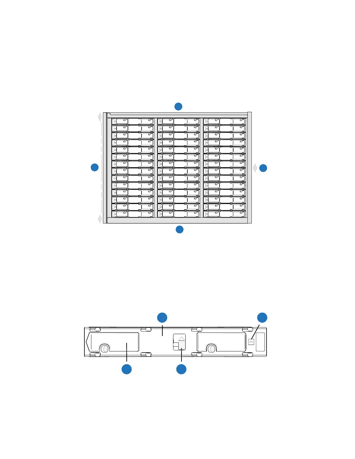
Figure 149 5U84 RAID or Expansion Chassis Drive Slots
2 Open the relevant drawer per the instructions provided in Opening a 5U84 Drawer on page 191.
3 Locate the DDIC to be replaced using any of the methods listed in step 1 above.
4 Locate the latch button (Item 3) and side latch (Item 4) on the DDIC as shown in Figure 150.
Figure 150 DDIC LED
2
1
3
4
0/42
2/44
1/43
3/45
4/46
5/47
6/48
7/49
8/50
9/51
10/52
11/53
12/54
13/55
14/56
15/57
16/58
23/65
18/60
19/61
20/62
21/63
22/64
41/83
17/59
25/67
26/68
27/69
28/70
29/71
30/72
31/73
24/66
37/79
38/80
35/77
39/81
33/75
34/76
36/78
40/82
32/74
1
Drawer 0/1 Front
2
Drawer 0/1 Left Side
3
Drawer 0/1 Rear (slides into chassis)
4
Drawer 0/1 Right Side
4
2
1
3
1
DDIC (longitudinal view - top face of carrier
2
Drive Fault LED
3
Latch Button (locked)
4
Side Latch
 Loading...


