System Overview 25
Refer to Figure 28 for all the 5U84 Raid chassis CRUs with CNC controllers.
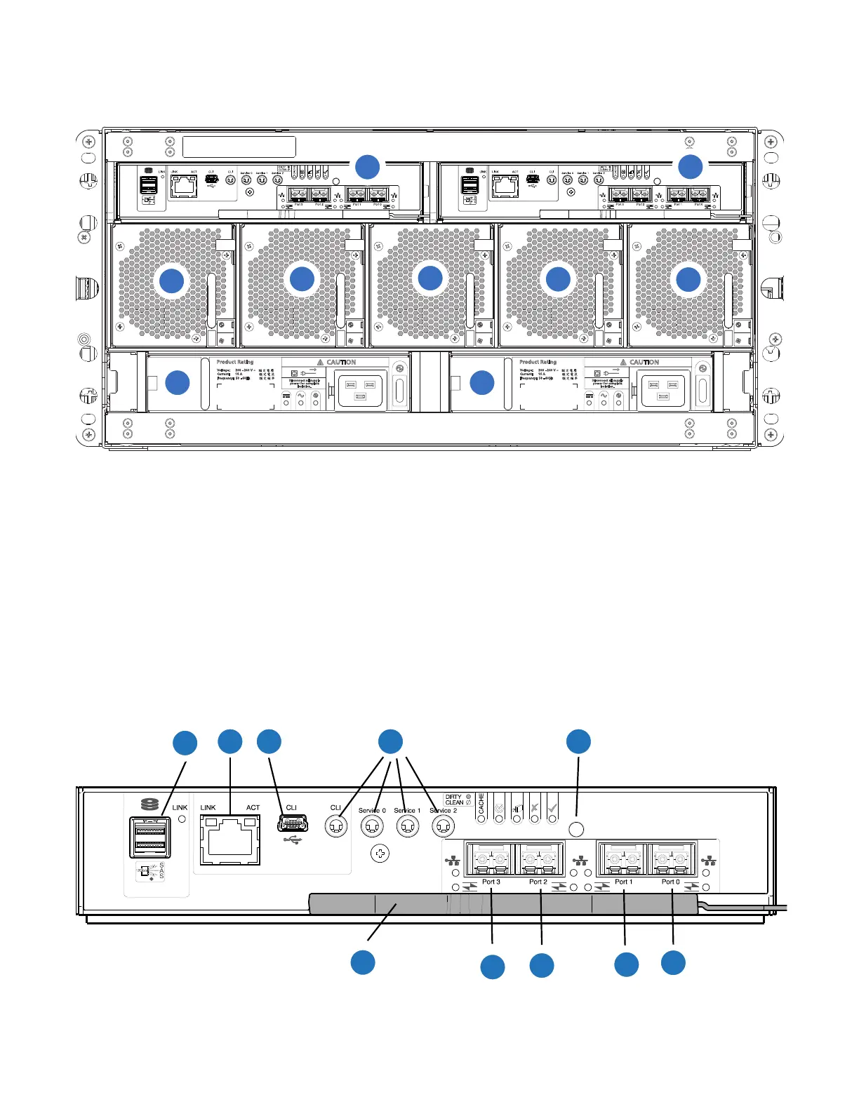
Figure 28 5U84 RAID Chassis Rear View (CNC Controllers)
CNC FC/iSCSI Controller
Callout 1, Figure 28, is the Controller A location. Callout 2 Figure 28, is the Controller B location. Both
controllers are shown in the closed/locked position.
Figure 29 provides a rear view of the CNC FC/iSCSI controller used in the 5U84-drive systems. You can
configure the CNC host interface ports (Ports 0, 1, 2 and 3) with 8/16Gb/s FC SFPs; 10GbE iSCSI SFPs;
or 1Gb/s RJ-45 SFPs.
Figure 29 CNC FC/iSCSI Controller
1
2
3
4
5
6
7
8 9
1
Controller A
2
Controller B
3
Fan 0
4
Fan 1
5
Fan 2
6
Fan 3
7
Fan 4
8
PSU 0
9
PSU 1
2 3 4 5
1
6
7
8
9
10
 Loading...


