LTE-A Module Series
EM120R-GL&EM160R-GL Hardware Design
EM120R-GL&EM160R-GL_Hardware_Design 25 / 79
In order to avoid damages to the internal flash, do not cut off the power supply directly when the module is
working. It is suggested that the power supply should be cut off after the module is shut down.
3.4. Turn-on and Turn-off Scenarios
3.4.1. Turn on the Module
Pulling up the FULL_CARD_POWER_OFF# pin will power on the module. The following table shows the
pin definition of FULL_CARD_POWER_OFF#.
Table 5: Pin Definition of FULL_CARD_POWER_OFF#
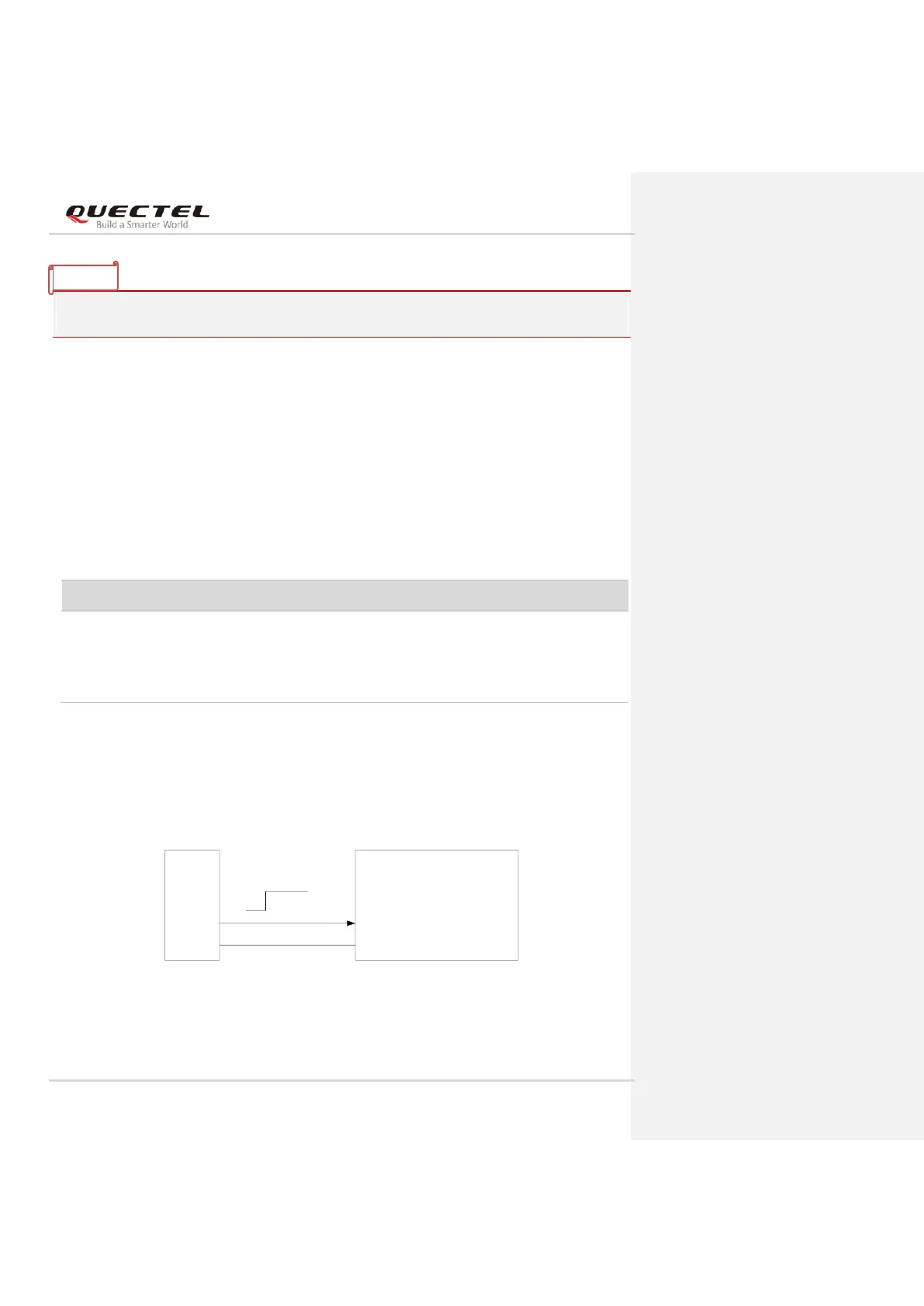
3.4.1.1. Turn on the Module with a Host GPIO
It is recommended to use a host GPIO to control FULL_CARD_POWER_OFF#. A simple reference circuit
is illustrated in the following figure.
Module
Host
GND
GND
GPIO
FULL_CARD_POWER_OFF#
1.8 V or 3.3 V
Figure 6: Turn on the Module with a Host GPIO
Turn on/off the module.
When it is at low level, the
module is powered off.
When it is at high level, the
module is powered on.
VIHmax = 4.4 V
VIHmin = 1.19 V
VILmax = 0.2 V