EasyManuals Logo

Quectel LTE-A Module Series User Manual

Quectel LTE-A Module Series
86 pages
To Next Page IconTo Next Page
To Previous Page IconTo Previous Page
Page #54 background imageLoading...
Page #54 background image
LTE-A Module Series
EM120R-GL&EM160R-GL Hardware Design
EM120R-GL&EM160R-GL_Hardware_Design 53 / 79
Table 26: List of EM160R-GL Configuration Pins
3.13.2. EM120R-GL configuration pins
Table 27: List of EM120R-GL Configuration Pins
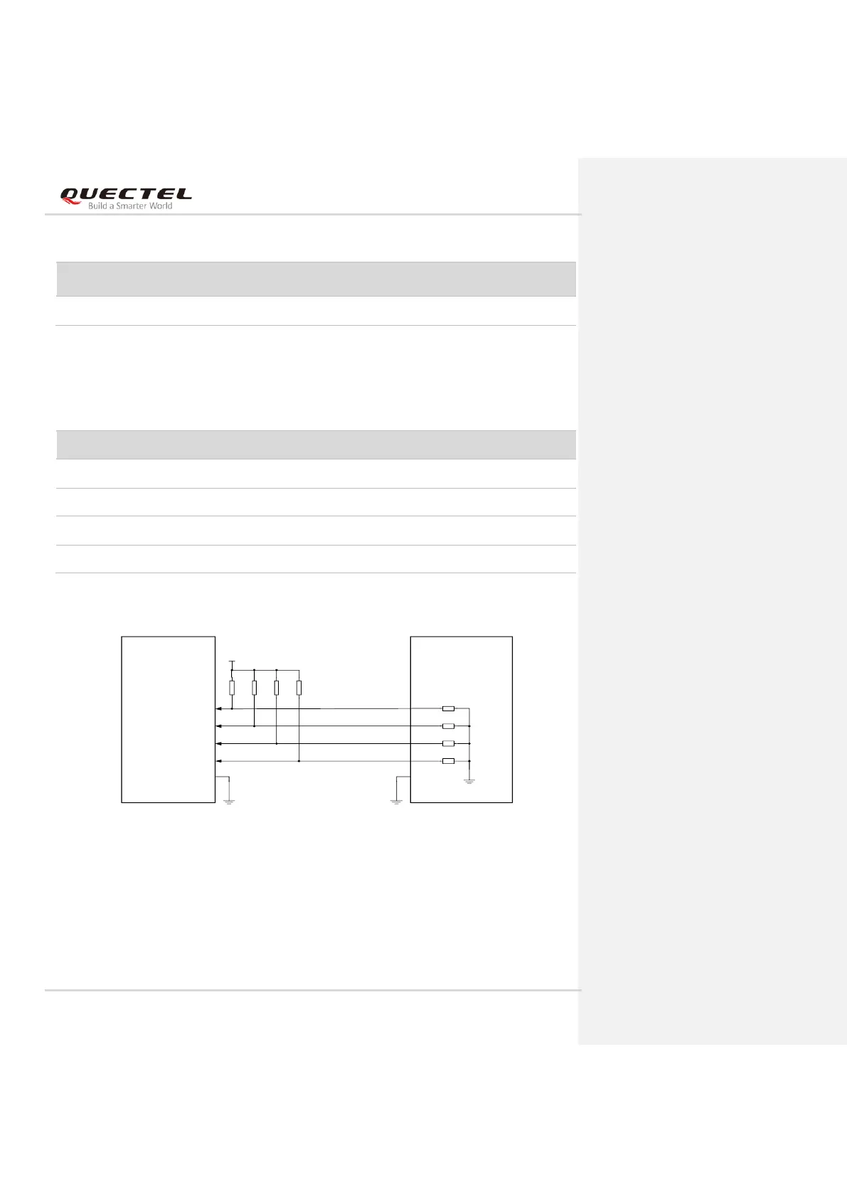
The following figure shows a reference circuit of these four pins.
Host EM120R-GL
CONFIG_0
CONFIG_1
CONFIG_2
CONFIG_3
GPIO
GPIO
GPIO
GPIO
21
69
75
1
VCC_IO_HOST
R1
100K
R2
100K
R3
100K
R4
100K
0Ω
NM-0Ω
NM-0Ω
0Ω
Note: The voltage level VCC_IO_HOST depends on the host side, and could be a 1.8 V or 3.3 V
voltage level.
Figure 31: Recommended Circuit of EM120R-GL Configuration Pins
Config_0
(Pin 21)
Config_1
(Pin 69)
Config_2
(Pin 75)
Config_3
(Pin 1)
Module Type and
Main Host Interface
Port
Configuration
NC
GND
NC
NC
Vender defined
N/A
Pin No.
Pin Name
Power Domain
Description
21
CONFIG_0
0
Connected to GND internally.
69
CONFIG_1
0
Connected to GND internally.
75
CONFIG_2
0
NC
1
CONFIG_3
0
NC

Table of Contents

Questions and Answers:

Question and Answer IconNeed help?

Do you have a question about the Quectel LTE-A Module Series and is the answer not in the manual?

Quectel LTE-A Module Series Specifications

General IconGeneral
BrandQuectel
ModelLTE-A Module Series
CategoryControl Unit
LanguageEnglish

Related product manuals