LTE-A Module Series
EM120R-GL&EM160R-GL Hardware Design
EM120R-GL&EM160R-GL_Hardware_Design 26 / 79
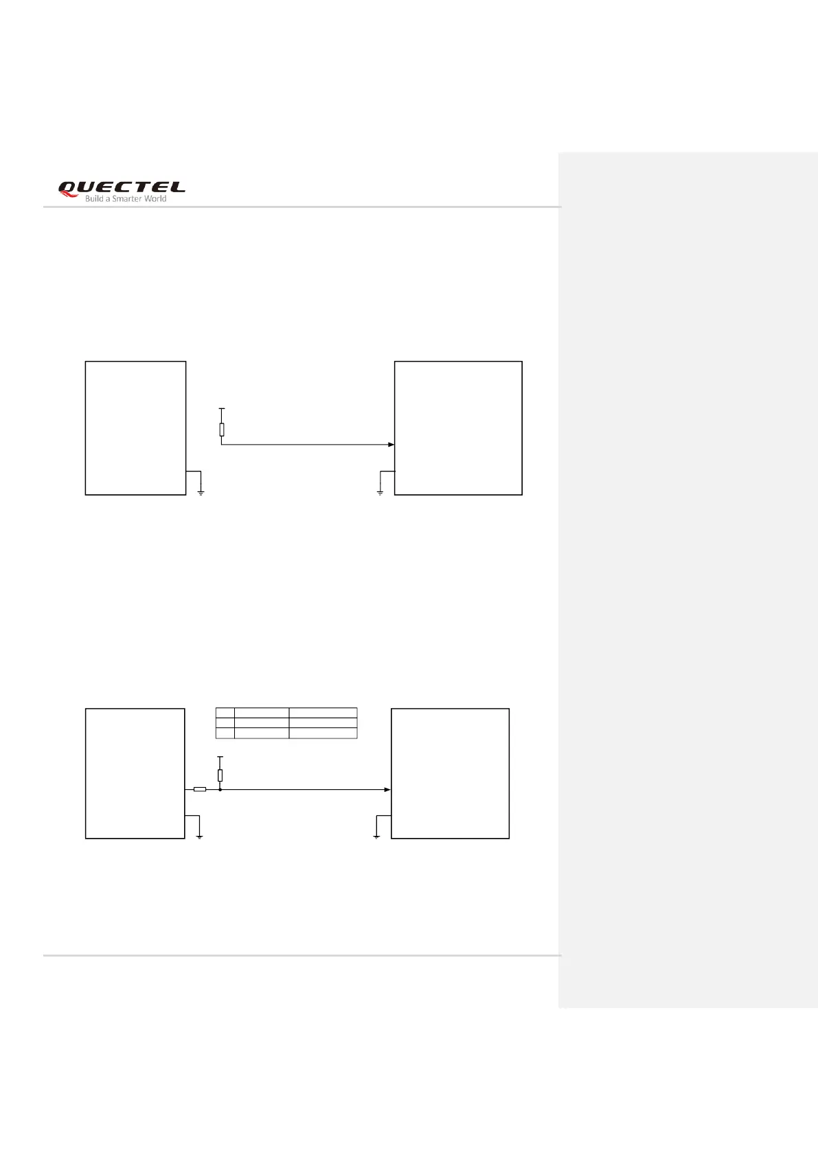
3.4.1.2. Turn on the Module Automatically
If FULL_CARD_POWER_OFF# is pulled up to VCC with a 5–10 kΩ resistor, the module will be powered
on automatically when the power supply for VCC is applied.
A reference circuit is shown in the following figure.
Host Module
FULL_CARD_POWER_OFF#
GPIO
VCC_IO_HOST
Notes:
1. The voltage of pin 6 should be no less than 1.19 V when it is at HIGH level.
2. The voltage level VCC_IO_HOST could be a 1.8 V or 3.3 V typically.
R1
10K
GND GND
6
Figure 7: Turn on the Module Automatically
3.4.1.3. Turn on the Module with Compatible Design
The following figure shows a compatible design to turn on the module automatically after power-up or by
host.
Host Module
FULL_CARD_POWER_OFF#
GPIO
VCC_IO_HOST
Notes:
1. The voltage of pin 6 should be no less than 1.19 V when it is at HIGH level.
2. The voltage level VCC_IO_HOST could be 1.8 V or 3.3 V typically.
Auto turn on Turn on by host
R1
R2
10 K
NM
NM
0 Ω
R1
10K
R2
NM_0Ω
GND GND
6
Figure 8: Turn on the Module with Compatible Design