LTE-A Module Series
EM120R-GL&EM160R-GL Hardware Design
EM120R-GL&EM160R-GL_Hardware_Design 32 / 79
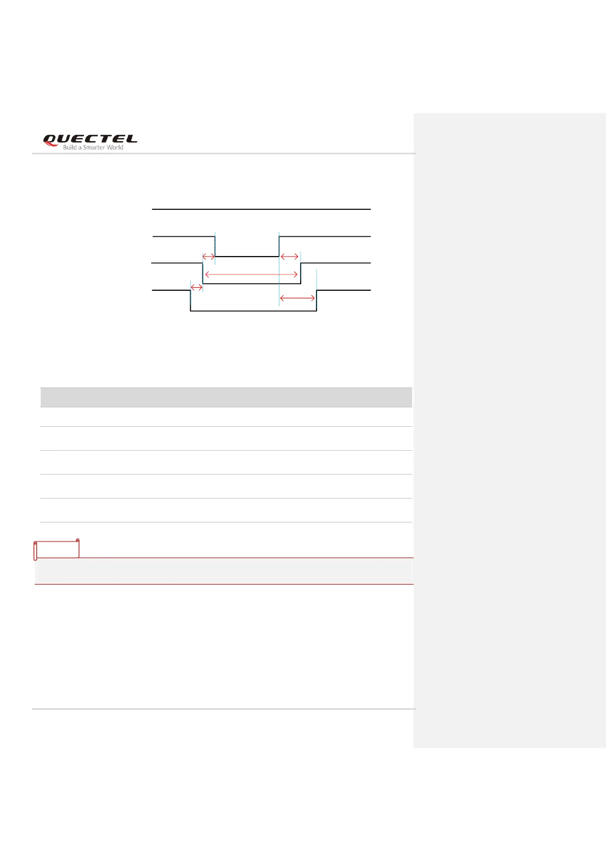
The reset scenario is illustrated in the following figure.
T1
T2
VCC (H)
FULL_CARD_POWER_OFF#
PCIE_RST_N
RESET#
T3
T4
T5
Figure 16: Timing of Resetting the Module
Table 9: Timing of Resetting the Module
Please ensure that there is no large capacitance on RESET# pin.
3.6. (U)SIM Interfaces
The (U)SIM interfaces circuitry meets ETSI and IMT-2000 requirements. Both 1.8 V and 3.0 V (U)SIM
cards are supported, and Dual SIM Single Standby* function is supported.
PCIE_RST_N should be asserted before RESET#.
RESET# should be asserted before
FULL_CARD_POWER_OFF#.
RESET# should be de-asserted after
FULL_CARD_POWER_OFF#
PCIE_RST_N should be de-asserted 100 ms after
FULL_CARD_POWER_OFF#.
RESET# should be de-asserted no longer than 700 ms,
otherwise the module would reset several times.