Section III - Airlogic Graphic Controller
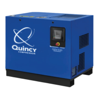
(i) Inputs
(ii) Discharge pressure
(iii) Inlet pressure
(iv) Emergency stop
(v) Pressure setting selection
• The screen shows a list of all inputs with their corresponding icons and readings.
• If an input is in warning or shutdown, the original icon is replaced by the warning
or shutdown icon respectively (i.c. the Stop icon and the Warning icon in the screen
shown above).
A small chart icon, shown below an item in the list means this input signal is shown on
the chart at the main screen. Any analog input can be selected.
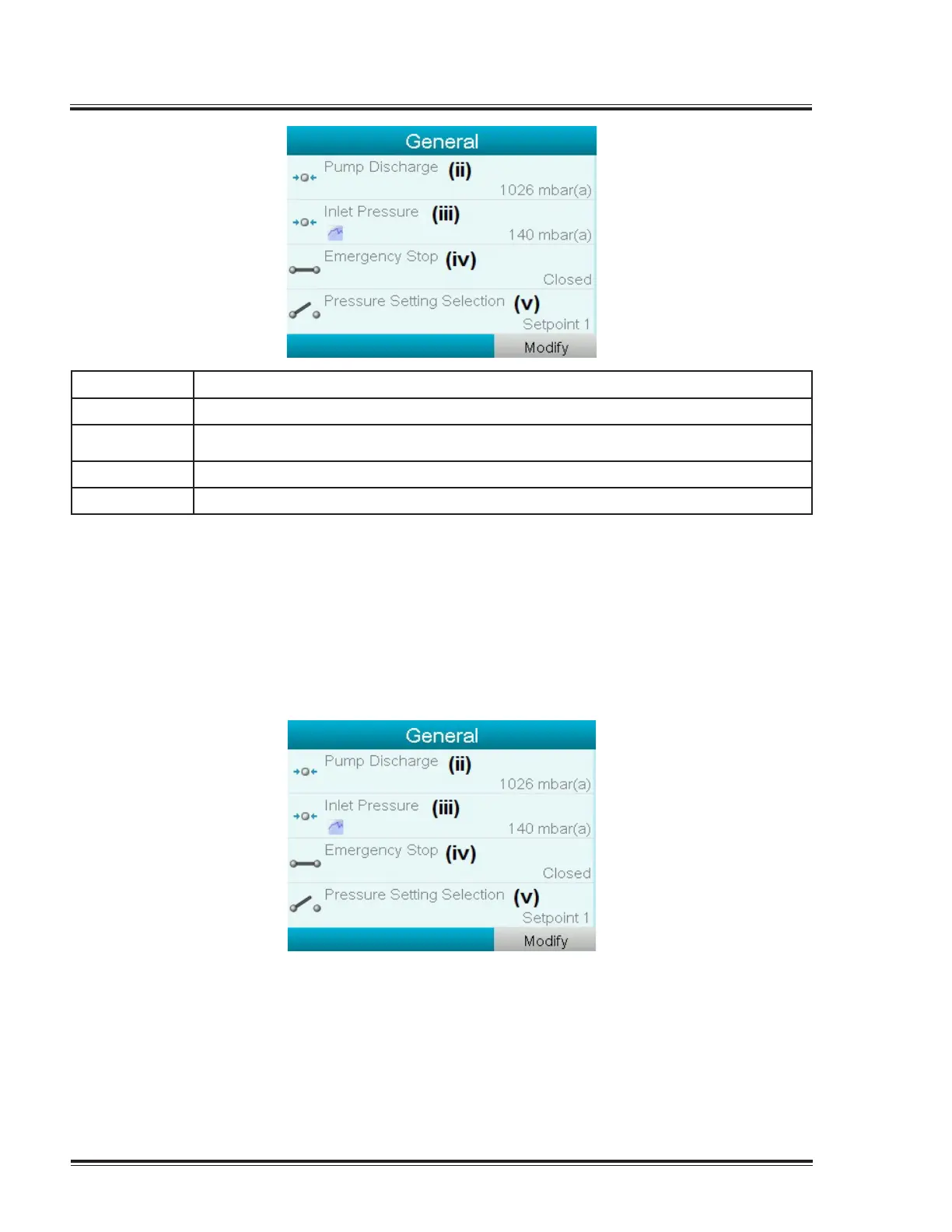
Selecting another input signal as main chart signal
With the Modify button active (light grey background in above screen), press the Enter
button on the controller. A screen similar to the one below appears:
The rst item in the list is highlighted. In this example, the inlet Pressure is selected (chart
icon). To change, press the Enter button again: a pop-up window opens:
28 Quincy Vacuum Pump-QSV Series
 Loading...