Radiolink Electronic Ltd
www.radiolink.com
The servo sub-menu includes two features:
• Real-time bar-graph display to demonstrate exactly what commands the transmitter is sending to
the servos. (This can be particularly handy in setting up models with complicated mixing functions,
because the results of each stick, lever, knob, switch input and delay circuit may be immediately
seen.)
• Servo cycle function to help locate servo problems prior to in-flight failures. (Channels 1-12)
View the result of
reassigning channel 6
from VR(A) knob to
three-position
SWITCH C
Cycle the channel 6
servo.
Complete desired programming
function.(Ex: in AUX-CH,move ch.6 to
SWITCH C)
for 1s .(If ADVANCE again) .
to SERVO , PUSH
Move each control to see the
operation.(Ex: SWITCH C in all positions)
C to center position. Note change in
position of ch.6 servo.
Prepare all servos to be cycled and cycle
Plug in servos. Power on.
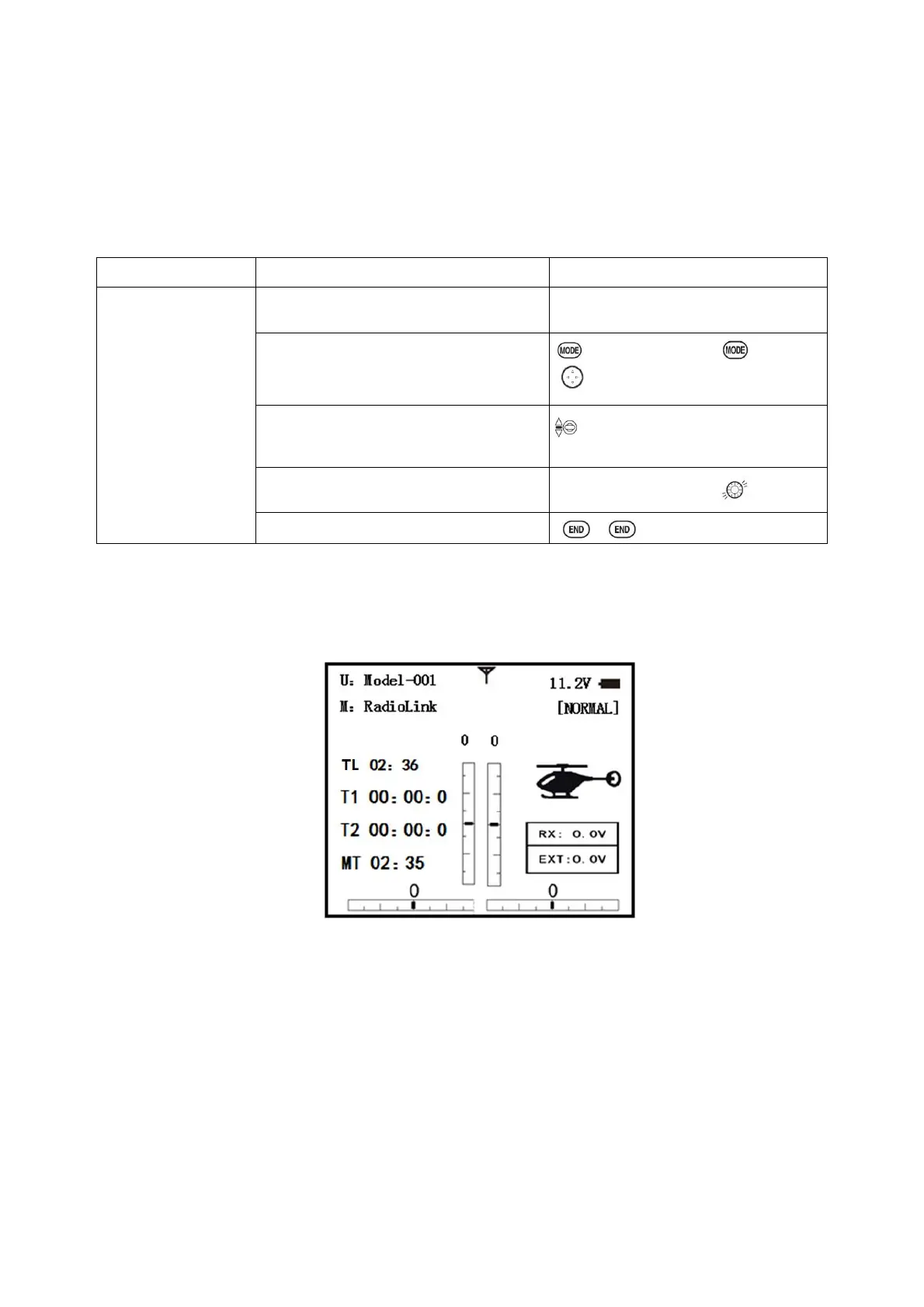
2.3.16 TELEMETARY
Signal strength and receiver voltage integrated into the radio transmitter. It is displayed as the
following configure, also it is in the sub menu RECEIVE.
Receiver voltage is shown as RX,
External voltage is shown as EXTY.
Find telemetry information: under BASIC MENU, select RECEIVE, presses PUSH to enter, you can
find the telemetry info, shown as below. RX is receiver voltage, EXT is external voltage. Also
temperature and engine speed (EXT, TEMPERATURE, RPM, and GPS all need telemetry sensor).
RSSI is signal strength, NULL is for no signal, and 0 is for max.
Connection of telemetry sensor: sensor of EXT, TEMPERATURE, RPM, GPS can connect one by
one with the receiver port DATA.

 Loading...