Preparing for Use
R&S
®
NRPxxS(N)
19User Manual 1177.5079.02 ─ 10
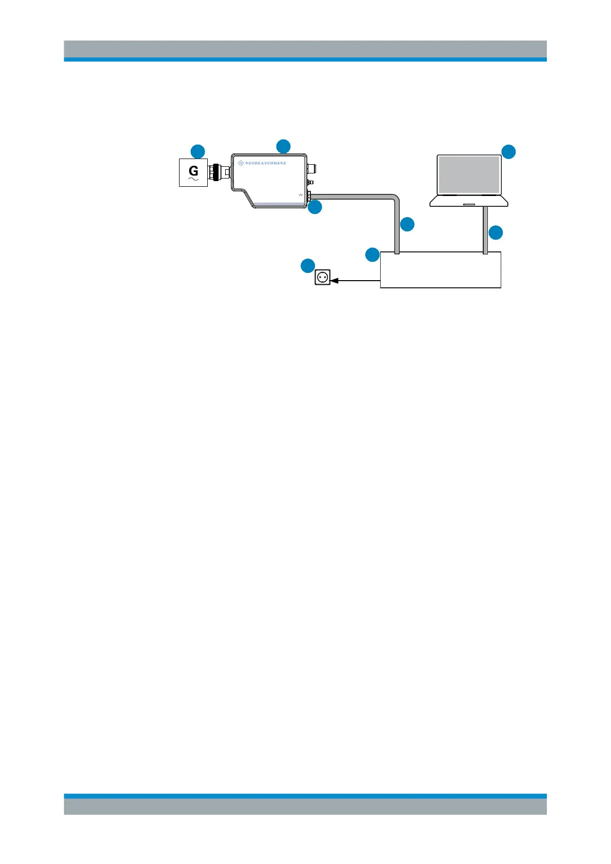
Setup with a PoE injector
1
4
6
5
2
3
HOST
INTERFACE
IN: 3 V or 5 V logic
OUT: min. 2 V into 50 Ω
max. 5.3 V
TRIG2
I/0
PoE
SMART SENSOR TECHNOLOGY
NRP
7
PoE Injector
8
Figure 3-5: Setup with a PoE injector
1 = Signal source
2 = LAN power sensor
3 = RJ-45 Ethernet connector
4, 7 = RJ-45 Ethernet cable
5 = PoE injector
6 = AC supply
8 = Computer
1. Connect the [RF] connector of the sensor to the DUT.
2.
NOTICE! Risk of sensor damage. Use only PoE power sourcing equipment (PSE)
according to IEEE standards 802.3af or IEEE 802.3at.
Otherwise your power sensor can get damaged.
Connect the RJ-45 Ethernet connector of the sensor to the output of the PoE injec-
tor.
3. Connect the PoE injector to a power supply.
4. Connect the computer to the input of the PoE injector.
5. Establish a network connection between the power sensor and the computer.
3.5.2.2 Establishing a Connection to the Network
There are two methods to establish a network connection:
●
Power sensor and computer are connected to a common network
(infrastructure network).
●
Power sensor and computer are connected only over the switch
(peer-to-peer network).
In both cases, you can address the LAN power sensor as follows:
●
Chapter 3.5.2.3, "Using Hostnames", on page 20
●
Chapter 3.5.2.4, "Assigning the IP Address", on page 21
Connecting to a Computer
 Loading...


