Power Sensor Tour
R&S
®
NRPxxS(N)
25User Manual 1177.5079.02 ─ 10
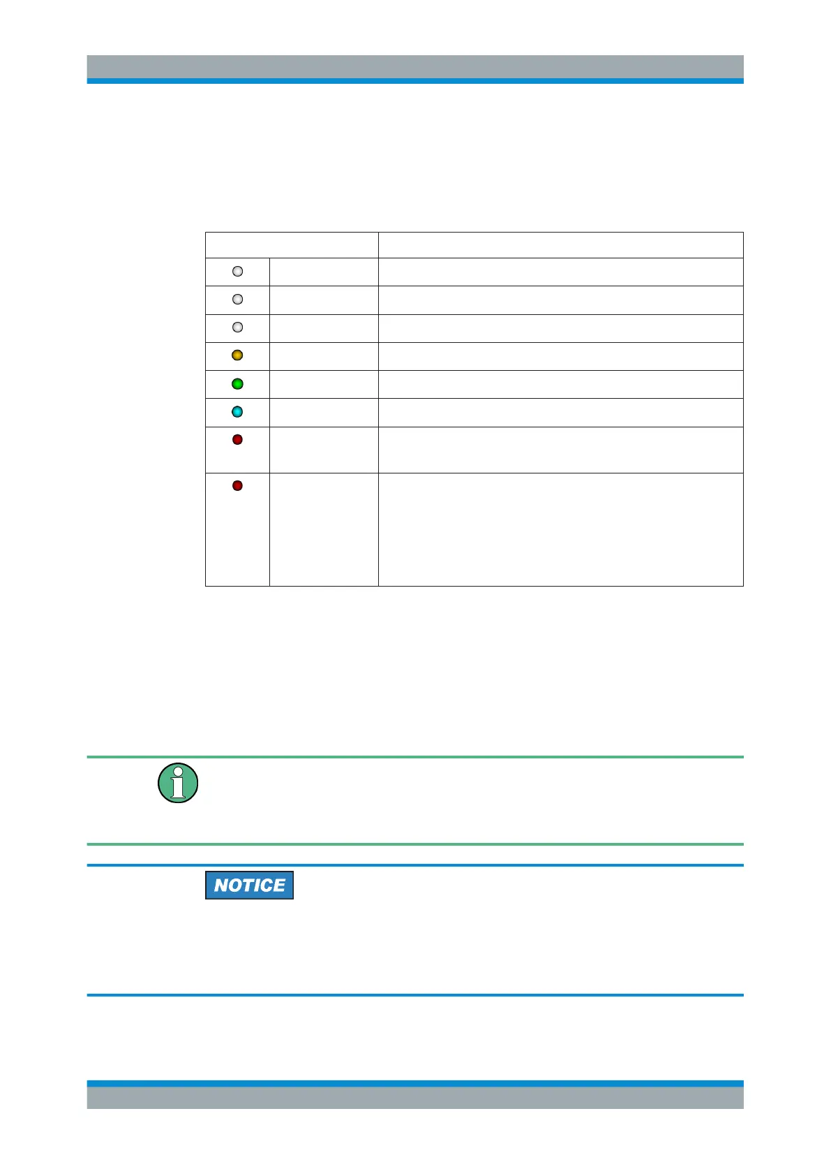
4.4 Status LED
The status LED gives information about the state of the power sensor. The following
states are defined:
Indication State
White Idle state. The sensor performs no measurement and is ready for use.
Flashing white Firmware update is in progress
Slow flashing white Sanitizing in progress
Yellow Wait for trigger state
Green Measuring state
Turquoise blue Zeroing is in progress
Slow flashing red Static error
You can query the error type with SYSTem:SERRor?.
Fast flashing red Critical static error
You can query the error type with SYSTem:SERRor?.
Note: If this state occurs after a firmware update, the update was not
successful. Perform the firmware update again.
See also Chapter 12.3, "Problems during a Firmware Update",
on page 176.
4.5 LAN PoE Interface
Available only for LAN power sensor.
An RJ-45 connector is used to connect the Ethernet interface of the power sensors to a
Local Area Network (LAN).
Ethernet interface requires PoE (Power over Ethernet)
When using the Ethernet interface of the power sensors, the electrical power has to be
provided by Power over Ethernet (PoE). In this case, it is not possible to provide the
power supply via the USB connector instead.
Risk of sensor damage
Use only PoE power sourcing equipment (PSE) according to IEEE standards 802.3af
or IEEE 802.3at.
Otherwise your power sensor can get damaged.
LAN PoE Interface
 Loading...


