CHAPTER 3
20 AccuFlow™ Vortex and AccuFlow™ HP+ Installation and Operation Manual
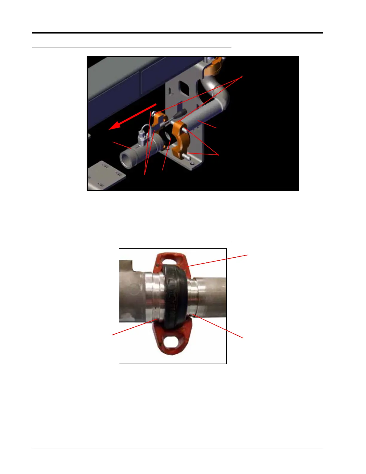
FIGURE 5. Flow Meter Assembly
5. Slide the flow meter into the end of the coupling gasket. Note the flow direction indicated on the flowmeter.
6. Place the two parts of the coupling clamp over the coupling gasket so the bolt holes are above and below the
outlet manifold.
FIGURE 6. Clamp Installation Detail
7. Using two 1/2” bolts and two 1/2” nuts to secure the coupling clamp to the flow meter and the outlet manifold.
8. Tighten the 1/2” nuts to 80 to 100 ft-lbs.
1/2” Bolts
Outlet
Manifold
Coupling
Gasket
1/2” Nuts
Coupling
Clamp
Flow Meter
F
l
o
w
D
i
r
e
c
t
i
o
n
Coupling Gasket
Groove
Groove