AccuFlow™ Vortex and AccuFlow™ HP+ Installation: One Inch Gauge Tree and Valve Assembly 27
ACCUFLOW™ VORTEX AND ACCUFLOW™ HP+ INSTALLATION
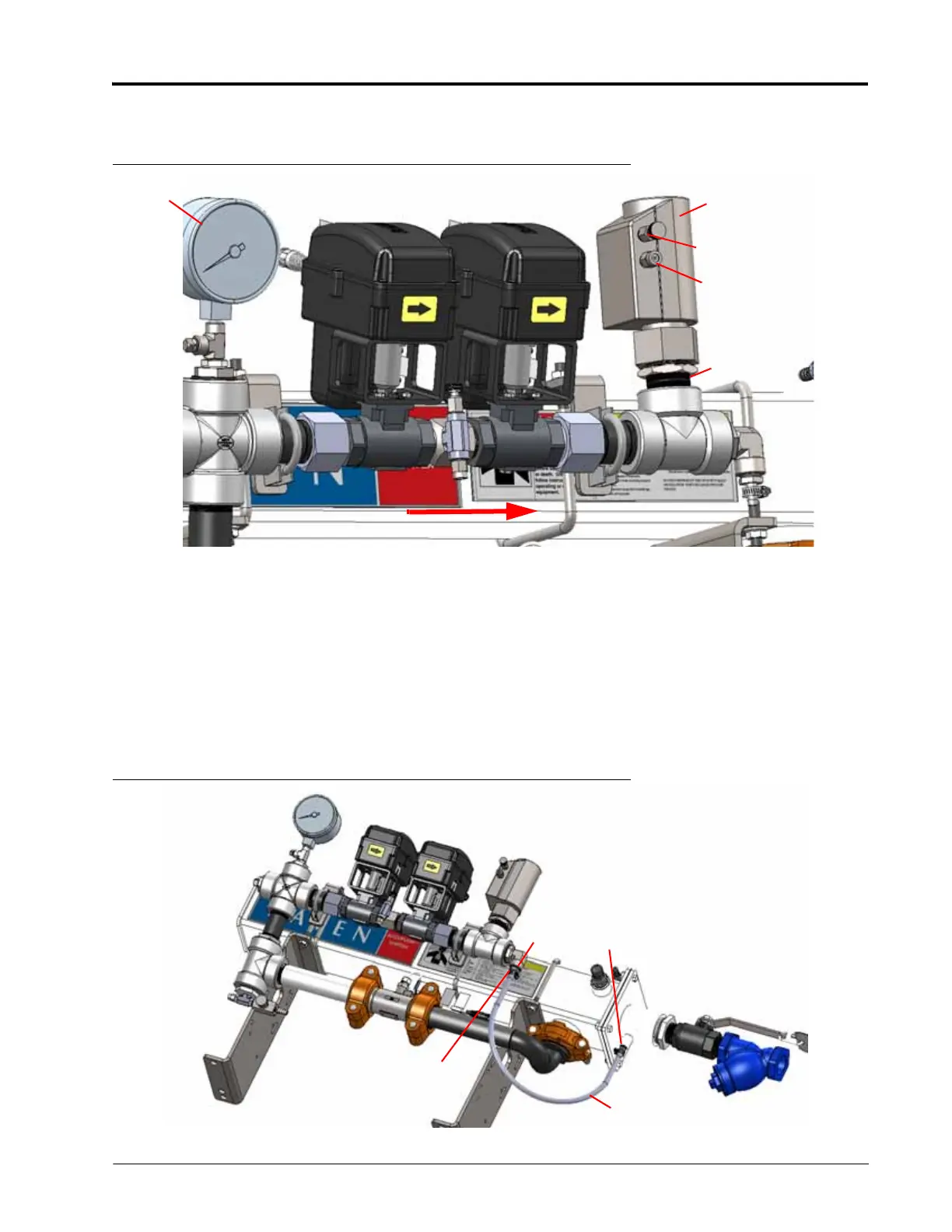
CHECK VALVE ASSEMBLY (FOR MULTIPLE SECTION VALVES ONLY)
FIGURE 13. Check Valve Assembly
1. Apply PTFE thread sealant to all threaded joints.
2. Install the pipe nipple into the top of the fitting tee.
3. Attach the check valve to the pipe nipple with the flow direction as shown in Figure 9.
NOTE: Refer to the spare parts list in Chapter 8, System Diagram and Replacement Parts for a list of
replacement parts.
REFRIGERANT LINE ASSEMBLY
FIGURE 14. Refrigerant Line Assembly
Check Valve
Gauge Tree
1/4” Bleed Valve
Flow Direction
Relief Valve
Pipe Nipple
Hose Barb
Fitting
Hose Clamp
Refrigerant
Line