AccuFlow™ Vortex and AccuFlow™ HP+ Installation: Manifold Assembly 29
ACCUFLOW™ VORTEX AND ACCUFLOW™ HP+ INSTALLATION
3. Attach the valve assembly to the end of the valve assembly to the 2” pipe nipple.
4. Secure the inlet manifold to the other end of the valve assembly.
5. Attach a strainer to each end of the inlet manifold. Ensure both strainers are in the same position.
6. Install and tighten a reducer bushing and a pipe nipple into the end of each strainer.
7. Install and tighten a check valve on each pipe nipple.
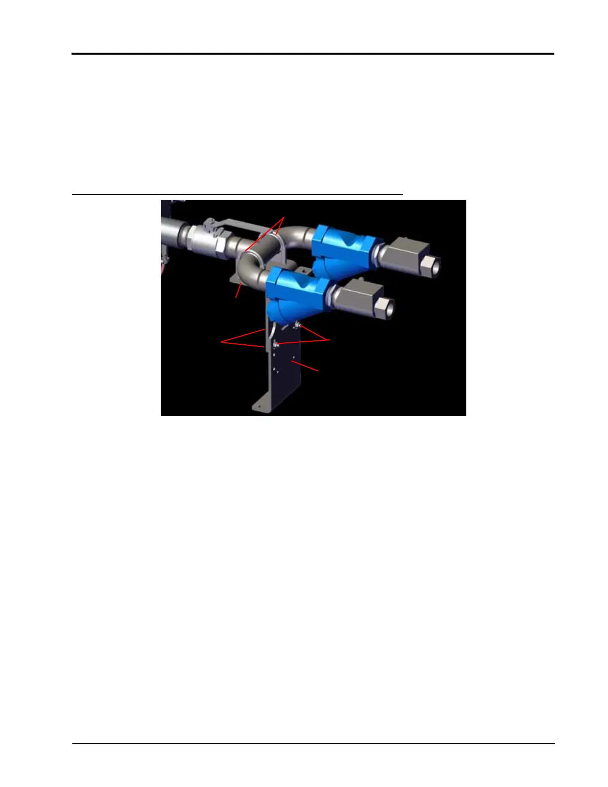
DUAL INLET MANIFOLD SUPPORT BRACKET INSTALLATION
FIGURE 17. Standard Inlet Manifold Support Bracket
1. Use three 3/8” bolts and 3/8” nuts to secure the mounting bracket to the inlet manifold support bracket.
2. Install two clamping u-bolts around the inlet manifold without installing the nuts.
3. Place the inlet manifold support bracket against the bottom of the inlet manifold (as shown in Figure 17).
4. Feed the threaded ends of the u-bolts through the holes on the inlet manifold support bracket.
5. Install the nuts on the threaded ends of the u-bolts on the underside of the inlet manifold support bracket.
Clamping U-Bolt
Inlet Manifold
Support Bracket
3/8” Bolt
3/8” Nut
Mounting
Bracket