CHAPTER 3
12 CAN Sidekick Pro Injection for Case IH 3/4XXX Installation and Operation Manual
FIGURE 2. Disconnecting the Battery
FIGURE 3. Field Computer Disconnect
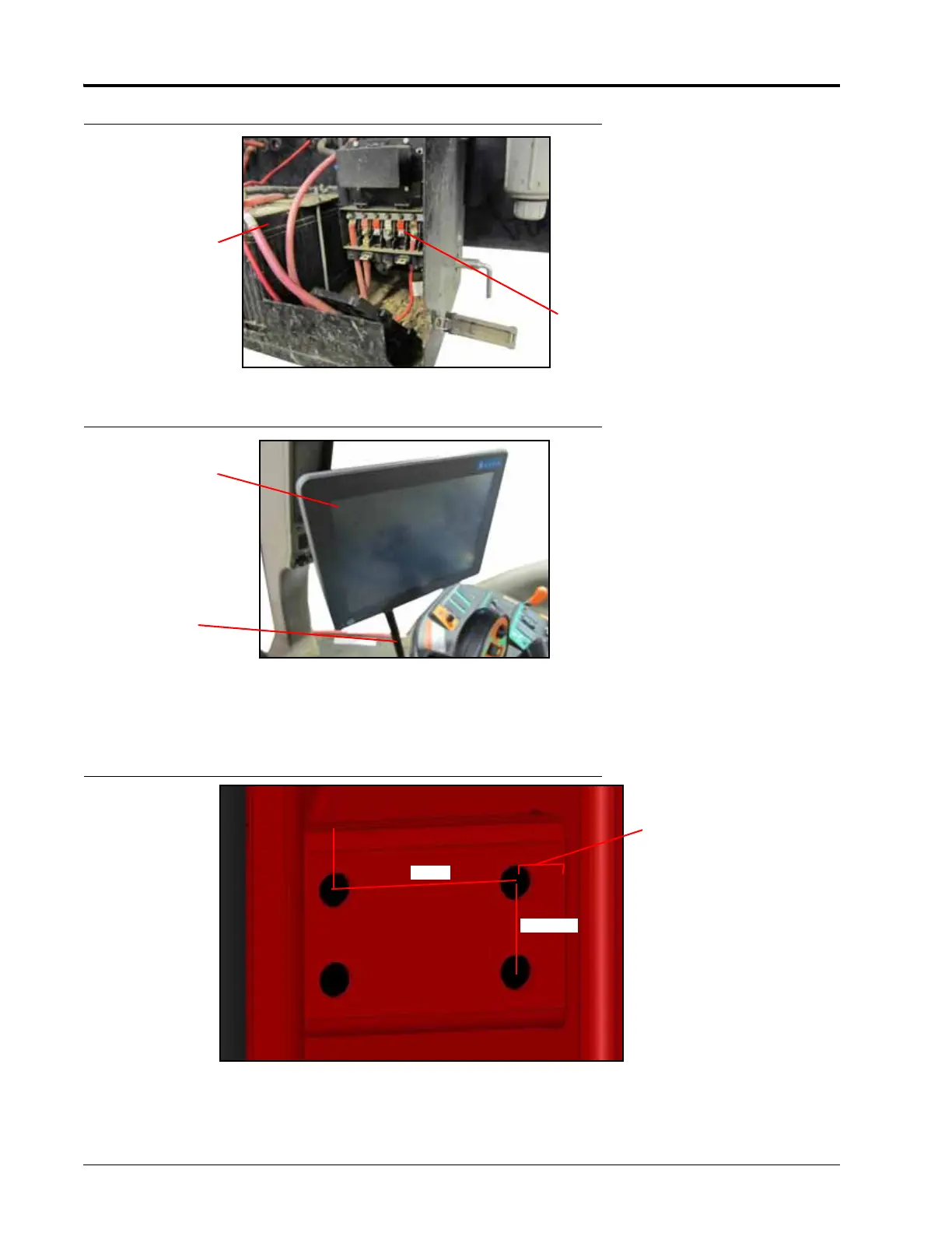
4. Use the supplied template (107-0172-334) to mark, center punch, and drill four 3/4” holes in the rear surface of
the left and right main frame towers cross tubes.
FIGURE 4. Main Frame Tower Cross Tube Hole Locations
5. For 33XX and 44XX machines, locate the lower support tab. Use the supplied template in the lower support tab
to mark and drill a 3/4” hole in the location shown on both sides of the machine. For 32XX machines that do
not have support tabs present, weld-on tabs have been provided.
Field Computer
Disconnect from