Installation: Installation 31
INSTALLATION
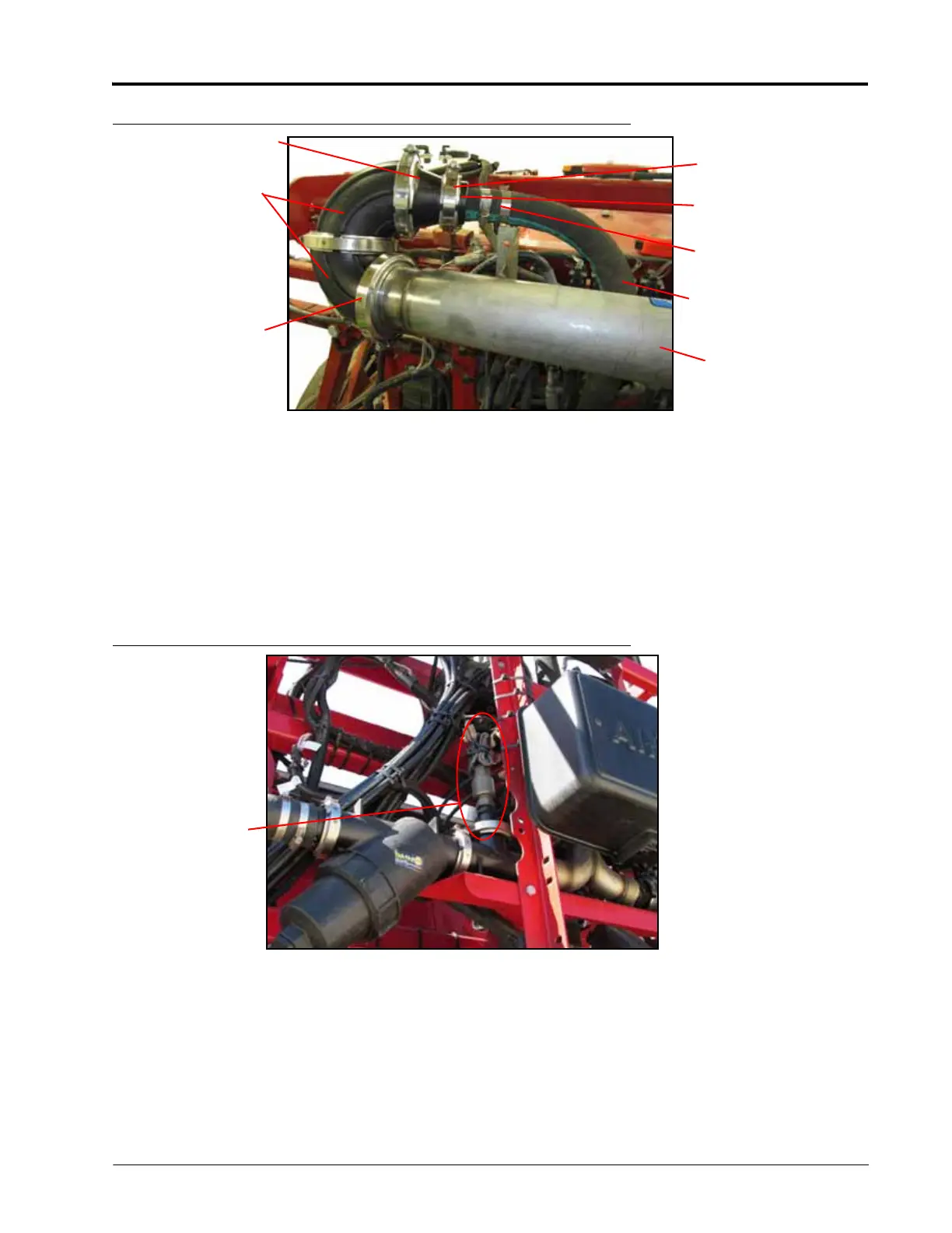
FIGURE 39. Mixer Outlet Plumbing Installed
MOVING AIM PRESSURE TRANSDUCER (IF NECESSARY)
NOTE: If the system is equipped with AIM Command, move the AIM pressure transducer to in front of the
carrier check valve on the mixer assembly.
1. Remove the 1/4” port plug from the M300 sweep elbow on the inlet of the injection mixer assembly.
2. Locate the AIM pressure transducer on the left hand side of the carrier distribution tee fitting. Disconnect the
electrical connection from the top of the transducer.
3. Remove the transducer from the M100 cap fitting.
FIGURE 40. AIM Command Pro Pressure Transducer
4. Install the 1/4” port plug into the open port on the cap fitting where the transducer was located. Seal threads
with the provided thread pipe thread sealant.
5. Install the transducer in the open gauge port fitting on the M300 sweep elbow.
6. Connect one end of the provided extension cable to the transducer.
NOTE: If the existing transducer and cable use 3-pin Metri-Pack connections, remove and replace the Metri-
Pack cable end with 3-pin Deutsch (not provided) to match the extension provided. Pin A (+5V
Pressure Power), Pin B (Pressure Ground), Pin C (Pressure Signal).
Hose to Boom
Plumbing
M300 Sweep Elbow
(2)
M300 Clamp (3)
and M300 Gasket
(3)
M220 Clamp (1) and
M220 Gasket (1)
Installed Mixer
and Check Valve
Assembly
M300 to M220
Reducing Coupling
1-1/2 to 3” Hose
Clamp
1-1/2” Hose Barb to
M220 (1) or 2” Hose
Barb to M220 (1)
AIM Command
Pro Pressure
Transducer