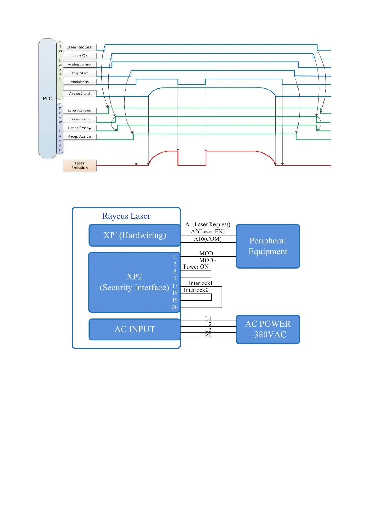
Figure 20 Timing diagram
6.6 Power Communication Setting in REM
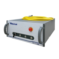
Figure 21 Wiring diagram of power internal control and laser emission external
Operations Steps:
a) Turn the knob switch on the rear panel to“ON”
b) Turn the key switch to“REM”
c) Short-circuit pin 8/9 on XP2
d) XP1-A1 connects to 24V
e) Connect XP1-A5 to 24V and turn on the guide laser; after checking the optics, connect XP1-A5
to 0V and turn off the guide laser


 To Next Page