Ellipse INSTALLATION GUIDELINES
70-00159-01-09 Proprietary Redline Communications © 2015 Page 26 of 52 April 29, 2015
3.6 Ellipse Lead-In Ethernet Connection
An Ethernet lead-in cable is supplied with the Ellipse system. This cable connects the
Ellipse Ethernet port to the PoE power injector located in the equipment cabinet. The
supplied cable is pre-terminated both ends with shielded RJ-45 connectors.
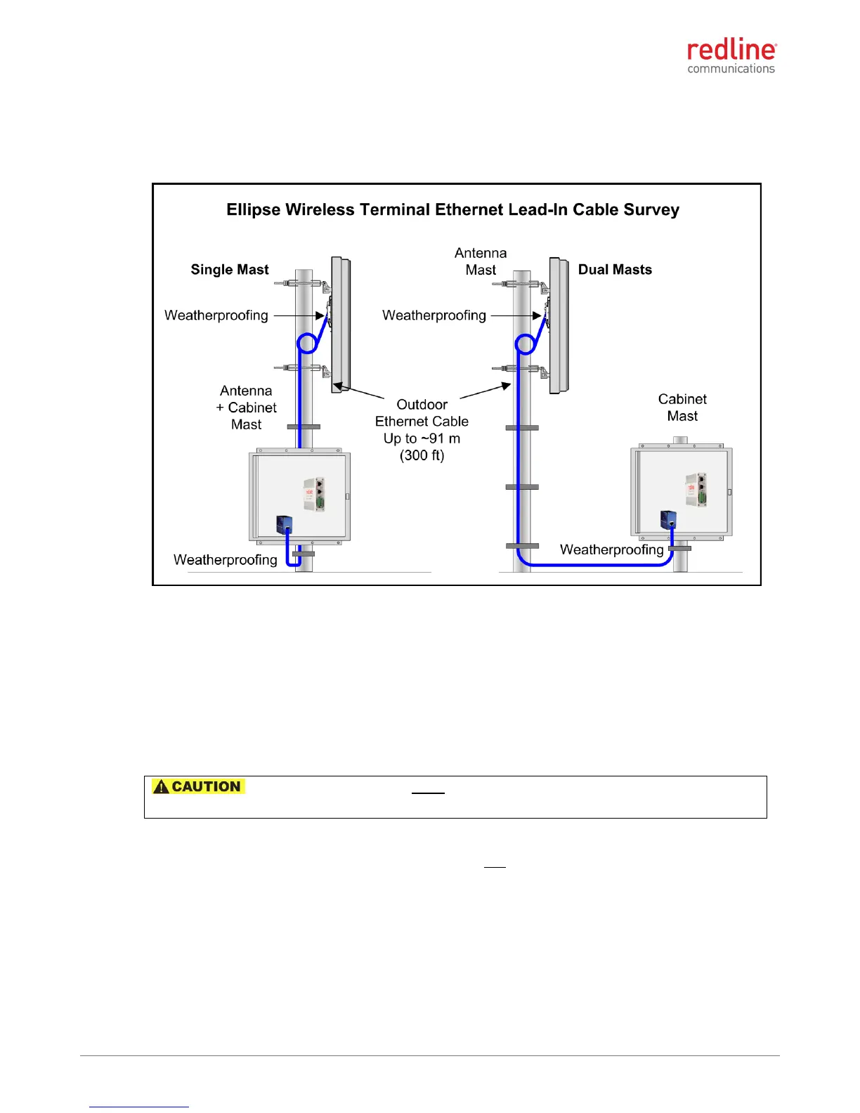
Figure 14: Site Survey: Ellipse Lead-In Ethernet Cable
Cable Length
The maximum recommended total length of the Ethernet cable is 100 m (330 ft) from the
wireless sector controller to the network equipment. Cable lengths exceeding this length
may affect system performance.
Surge Suppression
The Ellipse wireless sector controller features built-in surge suppression on the Ethernet
port.
: The system installer must install the surge/lightning protection at the
Ethernet cable ingress to the equipment cabinet.
Weatherproofing
The importance of proper weatherproofing can not be overstressed. The installer must
provide weatherproofing materials to be applied at the Ellipse Ethernet port and ingress
to the equipment cabinet. A gland is supplied for the Ellipse Ethernet port. The gland
must be installed and additional weatherproofing applied to provide adequate protection
against the weather.
Cable Supports
It is important to provide strain relief, drip loops and protection against vibration and
abrasion caused by the wind, sand etc. The installer must provide suitable cable
 Loading...