Ellipse INSTALLATION GUIDELINES
70-00159-01-09 Proprietary Redline Communications © 2015 Page 46 of 52 April 29, 2015
The following table lists the pinout for the PoE and Ethernet ports.
Table 16: Reference: Pinout for POE and ETH Ports
LED Indicators
Use the following table to determine the current mode of operation.
Table 17: Reference: DC-DC PoE LED Indicators
AF Mode active (~13W) (e.g., AN-80i)
AF Mode: Over-load or short-circuit.
AT Mode active (~25W) (e.g., wireless sector
controller)
AT Mode: Over-load or short-circuit.
Input voltage out-of-range or
PoE over-temperature
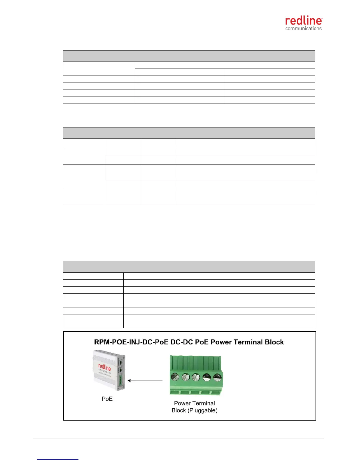
DC power Connections
The DC supply connections are located on the front panel. This is a keyed Buchanan
796864-5 (or equiv.) connector accepting 12 to 24 AWG wires. Dual isolated floating
power supply inputs are provided to accommodate deployments with backup power
(e.g., A + B battery banks). All power inputs include overvoltage and reverse polarity
protection.
Table 18: Reference: DC-DC PoE Power Connections
Positive and negative input for primary power supply.
Positive and negative input for secondary power supply.
Common system ground. This sector controller is connected directly to
the chassis and the ground lug on the back of the PoE.
LED is on when power is detected on either V1 or V2 pairs.
Power / Ground: #12 to #24 AWG
Chassis Ground: #10 Lug
 Loading...