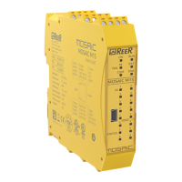
MODULAR SAFETY INTEGRATED CONTROLLER MOSAIC
8540780 • 10/07/2020 • Rev.38 3
MASTER ENABLE .................................................................................................. 35
NODE SEL ............................................................................................................ 35
PROXIMITY INPUT FOR SPEED CONTROLLER MV ..................................................... 36
Configuration With Interleaved Proximity .................................................. 36
RESTART_FBK ...................................................................................................... 37
OUTPUTS........................................................................................................ 38
OUT STATUS (SIL 1/PL c) ...................................................................................... 38
OUT TEST ............................................................................................................ 38
OSSD SAFETY OUTPUTS .................................................................................. 38
IMPORTANT NOTE CONCERNING OSSD SAFETY OUTPUTS .......................... 38
OSSD (M1, MI8O2, MO2, MO4) ............................................................................. 39
OSSD (M1S, MI8O4, MO4L) ................................................................................... 39
OSSD (MO4LHCS8) ............................................................................................... 41
OSSD OUTPUTS CONFIGURATION ......................................................................... 42
SAFETY RELAYS (MR2, MR4, MOR4, MOR4S8) ........................................................ 43
Characteristics of the output circuit. ..................................................................... 43
MR2/MR4/MR8 internal contacts diagram ............................................................. 43
Example of MR2 module connection with static OSSD outputs of a module M1 ....... 44
Switching operation timing diagram. .................................................................... 45
TECHNICAL FEATURES ................................................................................................................................ 46
GENERAL SYSTEM CHARACTERISTICS .................................................................... 46
Safety level parameters ............................................................................ 46
General data ............................................................................................ 46
Enclosure ................................................................................................. 47
M1 module .............................................................................................. 47
M1S module ............................................................................................. 48
MI8O2 module ......................................................................................... 48
MI8O4 module ......................................................................................... 48
MI8 - MI16 modules................................................................................. 49
MI12T8 module........................................................................................ 49
MO2 - MO4 modules ............................................................................... 49
MO4L module .......................................................................................... 49
MOS8 MOS16 modules .......................................................................... 50
MR2 - MR4 MR8 modules ...................................................................... 50
MOR4 MOR4S8 module .......................................................................... 50
MO4LHCS8 module .................................................................................. 51
MV0 - MV1 - MV2 modules ...................................................................... 51
MA2, MA4 module ................................................................................... 52
MECHANICAL DIMENSIONS.............................................................................. 53
LED INDICATORS (Normal Operation) .............................................................. 54
Master M1 (Figure 16) .......................................................................................... 54
Master M1S (Figure 16) ........................................................................................ 55
MI8O2 (Figure 18) ............................................................................................... 56
MI8O4 (Figure 18) ............................................................................................... 57
MI8 (Figure 20) .................................................................................................... 58
MI12T8 (Figure 22) .............................................................................................. 59
MI16 (Figure 22) .................................................................................................. 60
MO2 (Figure 23) .................................................................................................. 61
MO4 (Figure 24) .................................................................................................. 62
MO4L (Figure 18)................................................................................................. 63
MOR4 (Figure 26) ................................................................................................ 64
MOR4S8 (Figure 27) ............................................................................................. 65
MOS8 (Figure 28) ................................................................................................ 66
MOS16 (Figure 29)............................................................................................... 67
MV0, MV1, MV2 (Figure 30).................................................................................. 68

 Loading...