— English Reflexomat with Touch controller — 06.07.2016 - Rev. B
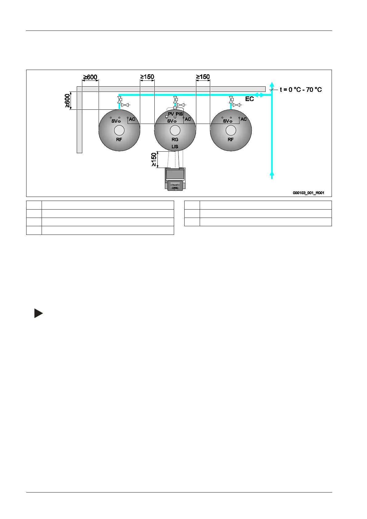
The following describes the exemplary installation of the control unit before the primary tank and the connection of two secondary
tanks. Proceed accordingly for other installation variants.
RF Secondary tank PIS Pressure sensor
RG Primary tank AC Compressed air line
SV Safety valve EC Expansion line
PV Solenoid valve
To ensure the proper function of the "LIS" level sensor, you must use the supplied hose to flexibly connect the primary tank to the
system.
The "EC" expansion line provides secure locking and emptying for primary tank and the optional secondary tanks. If more than one tank
is used, a collective line to the system is installed.
Use points with temperatures between 0 °C and 70 °C to connect to the system. This is the return of the generator in heating systems
and the flow in refrigeration systems.
At temperatures below or above 0 °C – 70 °C, you must install in-line vessels between the system and the Reflexomat.
Notice!
For details regarding the switching of Reflexomats
or in-line vessels and the dimensions of the expansion lines, please see
the planning documents. More information is also provided in the Reflex Planning Guide.