21
Orientation of the NC1 system
Throughout this guide it has been assumed that the NC1 system is
installed with the laser beam parallel to the X-axis. Length
measurements are made from the Z-axis and radial measurements
are made from the Y-axis.
If your system has been installed in a different orientation, you must
make the necessary adjustments to the axes used for length
measurement and radial measurement (for details, see manually-set
parameters RENC[21], RENC[22], and RENC[23].
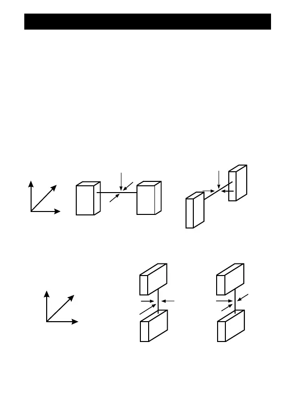
Orientation of the NC1 system
X-axis beam
Y-axis beam
RENC[21] = 1
RENC[22] = 2
RENC[23] = 3
RENC[21] = 2
RENC[22] = 1
RENC[23] = 3
Z
Y
X
Z-axis beam (Special)
Z
Y
X
RENC[21] = 3
RENC[22] = 1
RENC[23] = 2
RENC[21] = 3
RENC[22] = 2
RENC[23] = 1
or