30 November, 1999 PCBS
6-15
Replacement
Adjustment
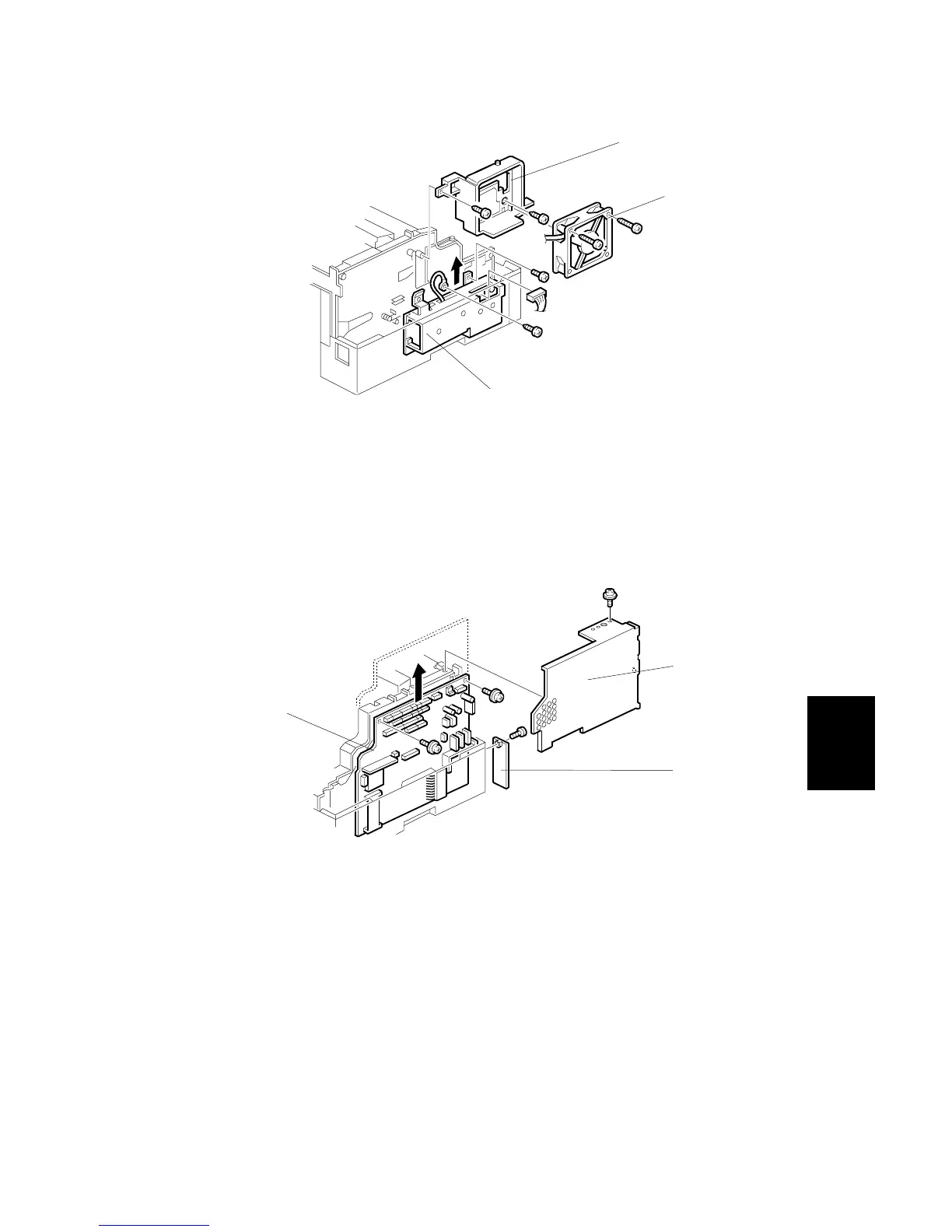
6.7.3 POWER PACK
First, remove the PSU.
A: Fan Motor (2 screws)
B: Fan Duct (2 screws)
C: Power Pack (1 screw, 1 screw with grounding wire, 1 connector)
6.7.4 FCU
After installing the new FCU, transfer the RAM data from the old FCU using service
function 12 (refer to section 4.1.24).
First, remove the Top Cover.
A: FCU Cover (2 screws, PC Interface Cover [C])
B: FCU (2 screws, 23 connectors)
NOTE: Turn on SW1 on the new FCU.
H545R532.WMF
H545R531.WMF
[A]
[B]
[C]
[A]
[B]
[C]
 Loading...