‐94‐
AS400 PORT
AS400 PORT
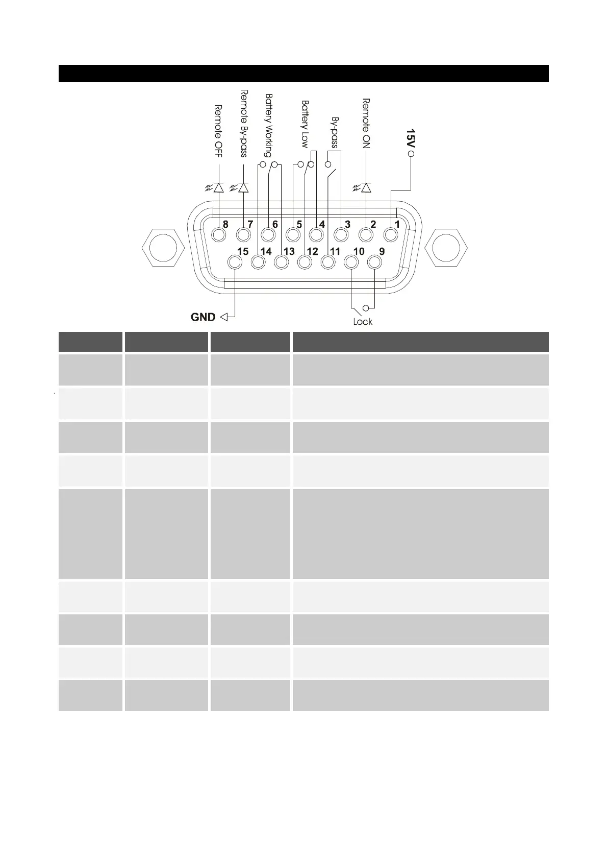
PIN # NAME TYPE FUNCTION
1 15V POWER Isolated auxiliary power +15V±5% 80mA max
15 GND POWER
Ground for the isolated power supplies (15V) and remote
controls (Remote ON, Remote BYPASS, Remote OFF)
2 REMOTE ON INPUT #1
Connect pin 2 with pin 15 for at least 3 seconds to switch on
the UPS
8 REMOTE OFF INPUT #2
Connect pin 8 to pin 15 and the UPS will immediately switch
off
7
REMOTE
BYPASS
INPUT #3
Connect pin 7 to pin 15 and power will transfer from the
inverter to the bypass. As long as the UPS is connected,
bypass operation will remain, even if the input mains cut off.
If the jumper is removed in the presence of power, the UPS
will begin operation via the inverter. If the jumper is removed
without power, the UPS will begin operation via batteries
4.5,12 BATTERY LOW OUTPUT #1 Signals that batteries are low when contact 5/12 is closed
(1)
6.13,14
BATTERY
WORKING
OUTPUT #2
Signals that the UPS is operating via batteries when contact
6/14 is closed
(1)
9.10 LOCK OUTPUT #3 Signals that the UPS is locked when the contact is closed
(1)
3.11 BYPASS OUTPUT #4
Signals that load power is passed through the bypass when
the contact is closed
(1)
NOTE: The figure shows contacts present inside the UPS, able to carry a max current of 0.5A at 42Vdc.
The position of the contacts indicated in the figure is without an alarm or signal present.
(1)
The output can be programmed with the configuration software.
The function shown is the default (factory setting).
 Loading...