RIGOL
© 2008 RIGOL Technologies, Inc.
User‟s Guide for Logic Signal Output Module
Output:
1. According to the above table, the output data would be: 1 1 0 0 0 0 1 0;
2. For RS232 protocol, the output sequence is “LSB”, then the output should be:
0 1 0 0 0 0 1 1;
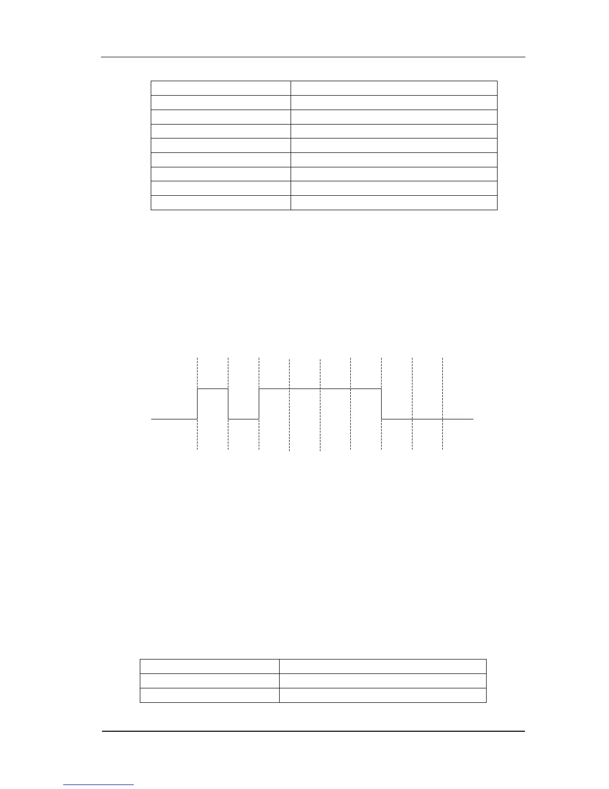
3. For RS232 protocol is negative logic output, in the output figure, “0” is
represented by high level and “1” is represented by low level as shown in the
figure below:
Note: For RS232 protocol, -15V~-5V is logic “1” and +5V~+15V is logic “0”.
Example 2:
Use PO protocol, output data length=4Bytes, data line=All, Offset=0, the other
parameters use default value, output user data as shown in Figure 2-26.
Explanation:
Offset=0 indicates the first data “1840” would be output. As data transmitting
parallel from the 16 channels, each channel will output 2 bits (total is 32 bits=4
Bytes). The data storage is shown in the following table.
Table 2-8 Data Storage (4Bytes)
 Loading...