Example 5: To Generate an IIC Digital Waveform Using
the PO Protocol
Operation steps:
1. Refer to Example 3 above, and use the default setup to output the IIC protocol
timing sequence as shown in the diagram below:
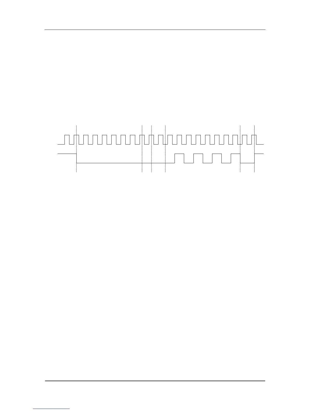
Figure 3-5 Time sequence of IIC protocol
From the above Figure 3-5, where SDA jumps from high to low when SCLK=1
indicates the “start” of the data output, and then; Address (0x00), Write
operation (0), response bit (High Z), 1 Byte data (01 code pattern), response
bit (High Z). The data output stops when SDA jumps from low to high when
SCLK=1.
2. In PO protocol, set “D0” as SCLK, “D1” as SDA and the code pattern as “User”.
Through editing the data in the user space, it can generate an IIC protocol
digital waveform.
1) First the SCLK data, because SDA jumps when SCLK transits from high or
low, SCLK data should not be set as 010101…, and it should be
001100110011…;
2) Since the IIC protocol has “high Z” output, the Mask Channel and the
Tri-state Channel should be set; D1 is the Tri-state Channel for data
output, and D2 is the Mask Channel.
3) Data in D0 and D1 can be edited with reference to Figure 3-5. While D2
is the Mask Channel, setting the corresponding bits of D1 (Tri-state
 Loading...