rletech.com WiNG-MGR v2 User Guide 43
3 Web Interface
3.6.4 Relay Outputs
The WiNG-MGR has two hard-wired relay outputs labeled K1 and K2. Use this tab to
individually configure the relay outputs. Use the individual sensor pages to designate when a
sensor alarm activates a relay output.
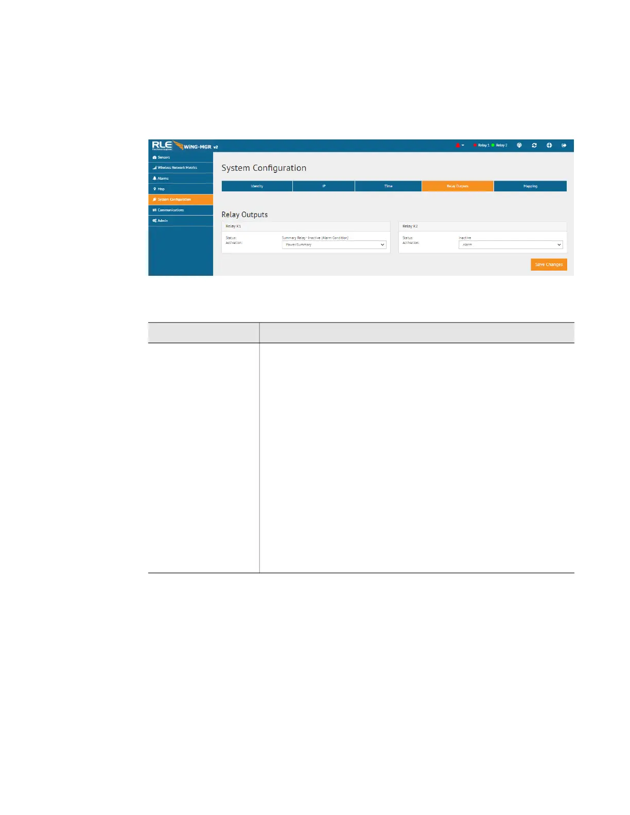
Figure 3.19
Relay Output Configuration
Option Description
Activation Each relay can be configured as an alarm relay, a latching alarm
relay, or a power/summary relay.
The power/summary option can be used to indicate basic status for
the WiNG-MGR:
• Relay will ACTIVATE when the unit has powered on and no
sensors are in alarm
• Relay will DE-ACTIVATE on a power loss or any alarm
condition (sensor value in alarm, low battery alarm or sensor
offline alarm)
Modbus support is provided for the relay outputs:
• Read the relay status with the 0x01 (Read Coil) command
• Reset LATCHED relays only with the 0x05 (Write single coil) or
the 0x15 (Write multiple coils) command
Default: Alarm
Table 3.9
Relay Output Configuration Options