rletech.com WiNG-MGR v2 User Guide 71
4
The register settings illustrated here are representative of only ONE sensor. Each sensor has a
unique register ID that can be found on that sensor’s Sensor Objects page (“Sensor Objects”
on page 34).
4.2.2 Function 06: Preset Single Register & Function 16:
Preset Multiple Registers
To set the relay outputs over Modbus, first set the relay activation mode must be set to Modbus
only. Do this in the web interface, at the bottom of the Digital IO Configuration page - Chapter
3, “Relay Outputs” on page 43. The master must then send a Preset Single or Preset Multiple
Register request packet.
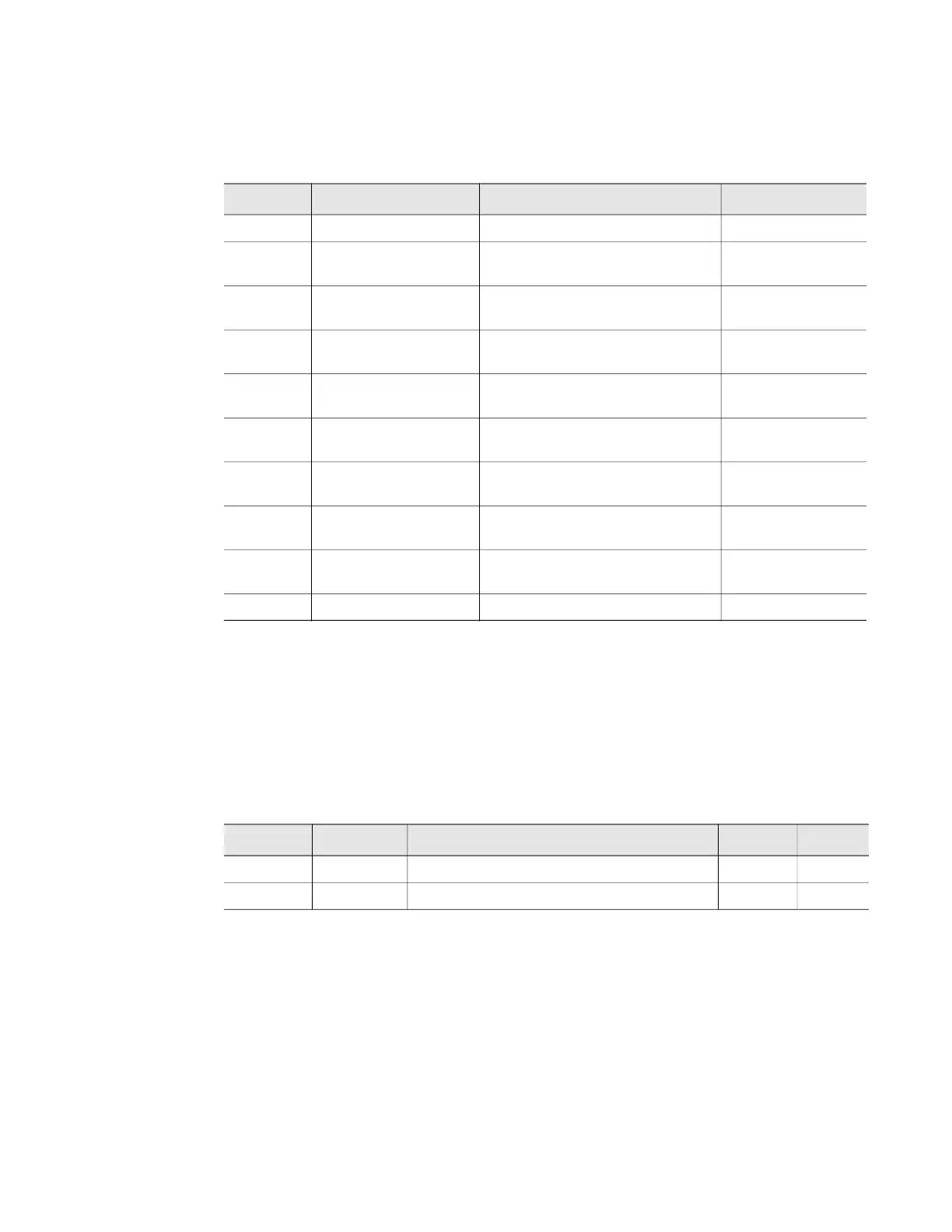
Register Name Description Units
40001 Id Sensor Identification number uint16
40002-
40003
Serial Number WiNG sensor serial number uint32 (Hex-ASCII)
40004-
40012
Sensor Name Descriptive text sensor name uint16 (Hex-ASCII)
40013 Converted Data #1 First data value converted by the
WiNG-MGR
int12
40014 Converted Data #2 Second data value converted by
the WiNG-MGR
int16
40015-
40016
Converted Data #3 Third data value converted by
the WiNG-MGR
int32
40017 Battery Level Battery voltage (in centivolts) or
percentage remaining
int16
40018 Service Status Bits8-4 = unused; bit3 = alarm;
bit2 = battery low; bit1 = offline
uint16 (Binary)
40019 Sensor Age Time since last transmission
received
uint16
40020 Offline Delay Time till the sensor reads offline uint16
Table 4.3
Read Output Registers
Register Name Description Units Range
49001 Relay K1 Relay 1 Activation: 1=active, 0=inactive uint16 0-1
49002 Relay K2 Relay 2 Activation: 1=active, 0=inactive uint16 0-1
Table 4.4
Preset Single and Multiple Registers